Table of Contents
Advertisement
Advertisement
Table of Contents

Related Manuals for Henco CU-REGK-24V


Summary of Contents for Henco CU-REGK-24V
- Page 1 CU-REGK CU-REGC...
-
Page 2: Table Of Contents
Contents 1 About these instructions ..........27 Validity, storage and forwarding of the instructions Symbols 2 Safety ................28 Intended use 2.2 General safety notes 3 Device overview ............. 30 4 Operation ............... 31 4.1 Setting the target temperature 4.2 Navigation and settings 4.2.1 Lifestyle functions menu 4.2.2 Settings menu 4.2.3 Service menu... -
Page 3: About These Instructions
About these instructions Validity, storage and forwarding of the instructions These instructions apply to the room thermostats of the following types: - CU-REGK-24V - CU-REGK-230V - CU-REGC-24V - CU-REGC-230V These instructions include information necessary for the operation of the devices. The room thermostats are designated as “Standard”, “Comfort”... -
Page 4: Safety
2 Safety Intended use The room thermostat controls, directly or via a connection unit, thermal actuators connected in a room-by-room temperature con- trol system. It is suitable for 24 V or 230 V components, depending on the variant. The unit serves for •... - Page 5 Intended use lack experience or knowledge. If necessary, these persons must be supervised by a person responsible for their safety or receive instructions from this person on how to use this unit. • Ensure that children do not play with this device. Children must be monitored if necessary.
-
Page 6: Eng 3 Device Overview
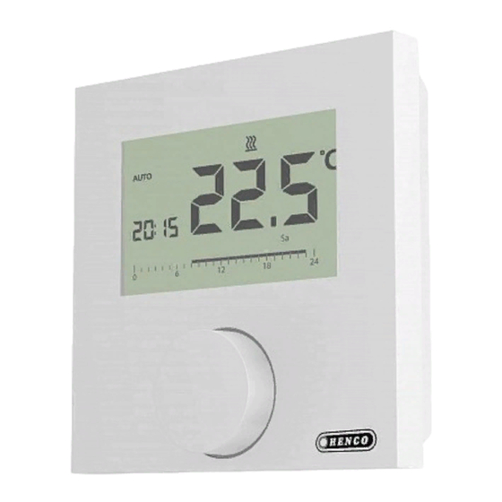
3 Device overview Display Mo Tu We Th Rotary control with turn/press mecha- nism and fine ratchet Room thermostats Symbol Meaning Symbol Meaning Lifestyle functions Temperature unit menu Target/ Settings menu actual temp. Heating Min. temperature Operating lock Max. temperature Make/confirm Switching off entry... -
Page 7: Operation
4 Operation WARNING Danger to life in case of swallowing! The rotary control can be taken off; children might swallow it. Setting the target temperature The target temperature is set by turning the rotary control to the left or to the right. Rotating to the left decreases the temperature, rotating to the right increases it. - Page 8 Setting the target temperature A basic level and three menus are available for navigation and set- tings: Basic level In the basic level, all room thermostats show the current actual tem- perature as well as active functions. The Control variant additionally is equipped with a clock function.
-
Page 9: Lifestyle Functions Menu
4.2.1 Lifestyle functions menu This menu allows the setting of the lifestyle functions. Depending on the room thermostat variant, the settings listed in the graphic are available. The following pages contain detailed information. • For the selection of an operating mode (day, night, auto- matic operation) only the inactive modes are available for selection. - Page 10 Lifestyle functions menu ¾ Open the menu selection by pressing. ¾ Select the menu Lifestyle functions. ¾ Activate the menu by pressing again. ¾ Select the desired function. Description Steps Day operation ¾ Confirm the selection by pressing. VDay operation is activated. VThe basic level is displayed.
- Page 11 Lifestyle functions menu Description Steps Automatic operation ¾ Confirm the selection by pressing. VAutomatic operation is acti- Komfort vated. The signal of an external system clock VThe basic level is displayed. (e. g. from a Control room thermostat) VControl: The time scale is activates day or night operation.
- Page 12 Lifestyle functions menu Description Steps Operating lock Activate Blocks the room thermostat. ¾ Confirm the selection by pressing. The actual temperature and all active functions are still displayed, the VThe operating lock is activated. possibility to change the target temper- VThe symbol is displayed.
-
Page 13: Ita 4.2.2 Settings Menu
4.2.2 Settings menu Extended settings can be made in this menu. Depending on the room thermostat type, the settings listed in the graphic are availa- ble. The following pages contain detailed information. If no operation is performed, the display returns to the basic level after approximately 30 seconds. - Page 14 Settings menu ¾ Open the menu selection by pressing. ¾ Select the settings menu. ¾ Activate the menu by pressing again. ¾ Select the desired setting. Description Steps Comfort temperature ¾ Confirm the selection by Heating pressing. Setting the target tempera- ¾...
- Page 15 Settings menu Description Steps External floor sensor ¾ Confirm the selection by Setting the minimum floor pressing. temperature. ¾ Make the setting. ¾ Confirm the entry. This function is displayed if the VThe display flashes in the connection of an external floor Settings menu.
- Page 16 Settings menu Description Steps Comfort programs ¾ Confirm the selection by In automatic operation there pressing. is a control with the switching VThe display switches to the times of the comfort programs: comfort program overview; the display indicates “day”. • Week (Mon–Sun) ¾...
- Page 17 Settings menu Description Steps Temperature correction ¾ Confirm the selection by Corrects a deviating measure- pressing. ment of the actual tempera- ¾ Set the correction value. ture of the internal sensor by ±2 °C in ¾ Confirm the entry. 0.1 °C increments. VThis is displayed in the Set- tings menu.
-
Page 18: Service Menu
4.2.3 Service menu CAUTION Damage to the installation! Faulty configuration can lead to errors and installation damage. ¾ Only authorised specialists may perform settings. Room thermostats Komfort and Control! An optimal tuning of the overall system can be reached by corre- sponding settings of the system parameters. - Page 19 Service menu Description Setting Heating system 0 = FBH St. Sets the existing heating system: 1 = FBH NE • Floor heating, standard (FBH St.) 2 = RAD • Floor heating, low energy (FBH NE) 3 = KON pas • Radiator (RAD) 4 = KON akt •...
- Page 20 Service menu Description Setting Signalling of switching output 0 = deactivated Signalises the control of switching outputs by a 1 = activated flashing heating resp. cooling symbol. Standard: 1 Control direction switching output 0 = NC Sets the control direction of connected actua- 1 = NO tors: •...
-
Page 21: Comfort And Protection Functions
5 Comfort and protection functions Comfort functions In order to increase the user comfort, the room thermostat includes functions for controlling the comfort temperature. 5.1.1 Smart Start/Smart Stop function Only room thermostat Control: The Smart Start/Smart Stop function (parameter 170) automati- cally calculates the required line-up times, so that the set comfort temperature is present at the start and end times of the comfort programs. -
Page 22: Maintenance
6 Maintenance Troubleshooting Display Meaning Possible elimination Internal sensor/room sensor Measuring temperature of • Remove external heat sources in the internal/external direct environment and wait until sensor exceeded the sensor has cooled down again. • Reposition the room sensor if necessary. -
Page 23: Cleaning
Maintenance Cleaning Only use a dry and solvent-free, soft cloth for cleaning.
Need help?
Do you have a question about the CU-REGK-24V and is the answer not in the manual?
Questions and answers