Chapters
Table of Contents

Related Manuals for Honda CBF190WH 2016


Summary of Contents for Honda CBF190WH 2016
- Page 1 Shop Manual CBF190WH 1. General Information 2. Fuel & Engine 3. Frame & Chassis 4. Electrical System This book is Specific Shop Manual. Refer to “Basic Shop Manual” for basic and common maintenance instructions. CBF190WH-G (2016)
-
Page 2: Table Of Contents
1. GENERAL INFORMATION A Few Words About Safety ················ 1-2 SPECIAL TOOL LIST ························ 1-14 How To Use This Manual ··················· 1-3 CABLE & HARNESS ROUTING ·········· 1-15 MODEL IDENTIFICATION ··················· 1-5 TECHNICAL FEATURES ··················· 1-22 SPECIFICATIONS······························ 1-6 MAINTENANCE SCHEDULE ·············· 1-23 TORQUE VALUE ······························1-11... -
Page 3: A Few Words About Safety
Any person who intends to use a replacement part, service procedure or a tool that is not recommended by Honda, must determine the risks to their personal safety and the safe operation of the vehicle. -
Page 4: How To Use This Manual
PUBLICATION ARE BASED ON THE LATEST PRODUCT INFORMATION AVAILABLE AT THE TIME OF APPROVAL FOR PRINTING. Honda Motor Co., Ltd. RESERVES THE RIGHT TO MAKE CHANGES AT ANY TIME WITHOUT NOTICE AND WITHOUT INCURRING ANY OBLIGATION WHATSOEVER. NO PART OF THIS PUBLICATION MAY BE REPRODUCED WITHOUT WRITTEN PERMISSION. - Page 5 Measure a resistance or check continuity. Measure a voltage. Measure an ampere. Refer to “Basic” Service Manual for the instruc- Use the Honda special tool. tion. LUBRICATION AND SEAL SYMBOL Apply molybdenum oil solution (mixture of an Use the recommend engine oil.
-
Page 6: Model Identification
GENERAL INFORMATION MODEL IDENTIFICATION • Model name: CBF190WH-G Code/Type Destination Argentina Colombia Latin America Chile Peru VEHICLE IDENTIFICATION NUMBER COLOR LABEL ENGINE SERIAL NUMBER... -
Page 7: Specifications
GENERAL INFORMATION SPECIFICATIONS GENERAL SPECIFICATIONS ITEM SPECIFICATION DIMENSIONS Overall length 1,982 mm Overall width 744 mm Overall height 1,041 mm Wheelbase 1,356 mm Seat height 771 mm Footpeg height 293 mm Ground clearance 138 mm Curb weight 140 kg Maximum weight capacity 170 kg FRAME Frame type... - Page 8 Engine oil capacity After draining 1.0 liter – After disassembly 1.2 liter – Recommended engine oil Honda “4-stroke motorcycle oil” or an equivalent motor oil. API service classification: – SG or higher JASO T903 standard: MA Viscosity: SAE 10W-30 Oil pump rotor Tip clearance 0.15...
- Page 9 GENERAL INFORMATION CYLINDER HEAD Unit: mm ITEM STANDARD LIMIT Cylinder compression 1,451 kPa at 450 rpm – Valve clearance 0.08 ± 0.02 – 0.24 ± 0.02 – Camshaft Cam lobe height 33.385 – 33.625 33.355 33.215 – 33.455 33.095 Rocker arm, Rocker arm shaft O.D.
- Page 10 GENERAL INFORMATION CRANKSHAFT/TRANSMISSION/BALANCER Unit: mm ITEM STANDARD LIMIT Connecting rod Side clearance 0.10 – 0.35 0.45 Radial clearance 0 – 0.008 0.05 Connecting rod small end I.D. 14.010 – 14.028 14.038 Crankshaft Runout – 0.03 Transmission Gear I.D. 20.000 – 20.018 –...
- Page 11 GENERAL INFORMATION BRAKE SYSTEM Unit: mm ITEM STANDARD LIMIT Front Specified brake fluid DOT 3 or DOT 4 – Brake disc thickness 3.8 – 4.2 Brake disc warpage – Master cylinder I.D. 12.700 – 12.743 – Master piston O.D. 12.657 – 12.684 –...
-
Page 12: Torque Value
GENERAL INFORMATION TORQUE VALUE • Each fastener should be tightened to the standard torque value except the fasteners specified torque value. • Q’TY: Quantity, DIA: Thread diameter (mm), TRQ: Tightening torque (N·m) STANDARD TIGHTENING TORQUE FASTENER TYPE FASTENER TYPE 5 mm hex bolt and nut 5 mm screw 6 mm hex bolt and nut 6 mm screw... - Page 13 GENERAL INFORMATION ALTERNATOR/STARTER CLUTCH ITEM Q'TY REMARKS Flywheel nut Apply engine oil. Starter clutch bolt Apply locking agent. Stator bolt CKP sensor bolt Apply locking agent. Alternator wire guide bolt Apply locking agent. CRANKCASE/CRANKSHAFT/BALANCER ITEM Q'TY REMARKS Mainshaft bearing setting plate bolt Apply locking agent.
- Page 14 GENERAL INFORMATION HANDLEBAR ITEM Q'TY REMARKS Handlebar pinch bolt Handlebar lever holder bolt Clutch lever pivot bolt Clutch lever pivot nut Left handlebar switch screw Right handlebar switch screw STEERING STEM ITEM Q'TY REMARKS Steering bearing adjustment nut – 3-21 Steering stem nut 3-21 REAR WHEEL...
-
Page 15: Special Tool List
GENERAL INFORMATION BATTERY/CHARGING SYSTEM ITEM Q'TY REMARKS Battery band bolt LIGHTING SYSTEM ITEM Q'TY REMARKS Headlight nut Front side cover screw Turn signal light nut License light screw OTHERS ITEM Q'TY REMARKS Throttle cable A adjuster lock nut (handlebar side) Seat lock assembly bolt Replace with a new one. -
Page 16: Cable & Harness Routing
GENERAL INFORMATION CABLE & HARNESS ROUTING To be butted. THROTTLE CABLE A 25° THROTTLE CABLE B Left Right INSIDE BOOT CONNECTORS: · HEADLIGHT 6P INSIDE BOOT CONNECTORS: · POSITION LIGHT 3P · TURN SIGNAL LIGHT WIRE CONNECTORS · RIGHT HANDLEBAR SWITCH 9P ·... - Page 17 GENERAL INFORMATION LEFT REAR TURN RIGHT REAR TURN SIGNAL WIRE SIGNAL WIRE HEADLIGHT WIRE POSITION LIGHT WIRE THROTTLE CABLE A To be butted. THROTTLE CABLE B To be butted. 1-16...
- Page 18 GENERAL INFORMATION BANK ANGLE SENSOR SENSOR 2P CONNECTOR 2P CONNECTOR MAIN WIRE HARNESS MAIN WIRE HARNESS SENSOR WIRE EOT SENSOR 2P CONNECTOR 20 – 25 mm 80 – 100° 15 mm MAIN WIRE 15 mm MAIN WIRE Maximum HARNESS Maximum HARNESS EVAP PURGE CONTROL...
- Page 19 GENERAL INFORMATION NEUTRAL SWITCH WIRE CKP SENSOR WIRE ALTERNATOR WIRE 1-18...
- Page 20 GENERAL INFORMATION NEUTRAL MAIN WIRE SWITCH WIRE HARNESS MAIN WIRE HARNESS MAIN WIRE HARNESS REGULATOR/ THROTTLE CABLE A RECTIFIER WIRE To be butted. To be butted. THROTTLE CABLE B IACV 4P CONNECTOR SENSOR UNIT 5P CONNECTOR 1-19...
- Page 21 GENERAL INFORMATION INJECTOR 2P CONNECTOR 15 mm Maximum MAIN WIRE MAIN WIRE HARNESS BATTERY POSITIVE (+) CABLE HARNESS FUEL TANK BREATHER HOSE 1-20...
- Page 22 GENERAL INFORMATION BRAKE/TAIL LIGHT WIRE INSIDE BOOT CONNECTORS: · LICENSE LIGHT 3P · BRAKE/TAIL LIGHT 3P · TURN SIGNAL LIGHT WIRE CONNECTORS LICENSE LIGHT WIRE LICENSE RIGHT REAR TURN LIGHT WIRE LEFT REAR TURN SIGNAL WIRE SIGNAL WIRE RIGHT REAR TURN LEFT REAR TURN SIGNAL WIRE SIGNAL WIRE...
-
Page 23: Technical Features
GENERAL INFORMATION TECHNICAL FEATURES FUEL PUMP SYSTEM WITH A FUEL FILTER BLOCKAGE REMINDER FUNCTION FUEL TANK BREATHER FILTER FUEL PUMP FUEL LEVEL BREATHER PASSAGE PUMP CHAMBER To FUEL INJECTOR FUEL FILTER : Air suction passage under fuel filter blockage : Air discharge passage under normal fuel filter condition : Fuel flow under normal fuel filter condition The fuel pump system of this model consists of the following components: –... -
Page 24: Maintenance Schedule
• * Should be serviced by a dealer, unless the owner has proper tools and service data and is mechanically qualified. • ** In the interest of safety, we recommend these items be serviced only by a dealer. • Honda recommends that a dealer should road test the vehicle after each periodic maintenance is carried out. NOTES: 1. - Page 25 MEMO...
- Page 26 2. FUEL & ENGINE FUEL LINE ······································· 2-2 CYLINDER HEAD····························· 2-15 FUEL PUMP UNIT······························ 2-4 CYLINDER/PISTON ·························· 2-21 FUEL TANK ······································ 2-6 CLUTCH/GEARSHIFT LINKAGE········· 2-22 AIR CLEANER ·································· 2-7 ALTERNATOR/STARTER CLUTCH····· 2-25 THROTTLE BODY ····························· 2-8 CRANKCASE/CRANKSHAFT/ BALANCER····································· 2-27 EVAP SYSTEM ································2-11 TRANSMISSION ······························...
-
Page 27: Fuel Line
FUEL & ENGINE FUEL & ENGINE FUEL LINE • This vehicle uses resin for the part of materials in the fuel feed hose. Do not bend or twist the fuel feed hose. • Fuel tank center cover 3-7 • Fuel pump 5P connector •... - Page 28 FUEL & ENGINE FUEL SUPPLY TEST • If the fuel in tank is sufficient but such symptom as poor en- gine performance, lack of fuel, or engine start failure exist, perform the following. • Perform the fuel pressure test. 2-3 •...
-
Page 29: Fuel Pump Unit
FUEL & ENGINE FUEL PUMP UNIT 12 N·m • Quick connect fitting (fuel pump side) 2-2 • Fuel tank 2-6 • Loosen the nuts in a crisscross pattern in several steps. • Carefully remove the fuel pump unit from the fuel tank to prevent damaging the fuel level sensor. •... - Page 30 FUEL & ENGINE FUEL FILTER • To prevent dirt and debris from entering the fuel pump unit, always clean it before disassembly. • Clean the fuel pump unit and fuel pump filter with clean gasoline. Never use commercially available carburetor cleaners. •...
-
Page 31: Fuel Tank
FUEL & ENGINE FUEL TANK • Quick connect fitting (fuel pump side) 2-2... -
Page 32: Air Cleaner
FUEL & ENGINE AIR CLEANER • Seat 3-3 • Discard the air cleaner element in accordance with the maintenance schedule. 1-23 • Replace the element any time if it is excessively dirty or damaged. • Rear shock absorber 3-25... -
Page 33: Throttle Body
FUEL & ENGINE THROTTLE BODY 12 N·m 4.5 N·m 4.5 N·m • Quick connect fitting (injector side) 2-2 • If the throttle body is changed, perform the TP sensor reset procedure. 2-10 • Throttle body cleaning and inspection... - Page 34 FUEL & ENGINE 2.1 N·m 5.1 N·m 2.1 N·m • The throttle body is factory pre-set. Do not disassemble in a way other than shown in this manual. • Do not loosen or tighten the white painted fasteners. Loosening or tightening it can cause throttle body malfunction. •...
- Page 35 FUEL & ENGINE TP SENSOR RESET PROCEDURE • Make sure that DTC is not stored in ECM. If the DTC is stored in ECM, TP sensor reset mode won’t start by follow- ing the procedure below. • Left side cover 3-4 •...
-
Page 36: Evap System
FUEL & ENGINE INJECTOR • Quick connect fitting (injector side) 2-2 EVAP SYSTEM • Side cover 3-4 2-11... - Page 37 FUEL & ENGINE • Fuel tank shroud 3-6 2-12...
-
Page 38: Lubrication System
• Check that the O-ring on the oil filler cap is in good LOWER condition, and replace it if necessary. • RECOMMENDED ENGINE OIL: Honda “4-stroke motorcycle oil” or an equivalent mo- tor oil. API service classification: SG or higher JASO T903 standard: MA... - Page 39 FUEL & ENGINE ENGINE OIL CHANGE • Drain oil completely. • Fill the crankcase with the recommended engine oil. • ENGINE OIL CAPACITY: 1.0 liter after draining 1.2 liter after disassembly 30 N·m ENGINE OIL STRAINER SCREEN/OIL PUMP 3.0 N·m •...
-
Page 40: Cylinder Head
FUEL & ENGINE CYLINDER HEAD • This service can be serviced with the engine installed in the frame. VALVE CLEARANCE • Inspect while the engine is cold (below 35°C). • After the valve clearance inspection, check the engine idle 10 N·m speed. - Page 41 FUEL & ENGINE CYLINDER HEAD COVER • Fuel tank shroud 3-6 2-16...
- Page 42 FUEL & ENGINE CAMSHAFT/ROCKER ARM • Set the piston to the TDC on the compression stroke. 2-15 • Install the special tool into the tensioner body and turn the tool clockwise until it stops. Hold the tensioner lifter by pushing the tool while aligning the tabs of the tool with the grooves of the tensioner lifter.
- Page 43 FUEL & ENGINE 30 N·m 7.4 – 12 mm 9.0 N·m • Camshaft/rocker arm 2-17 • Exhaust pipe/muffler 3-15 • Intake pipe mounting bolts/insulator 2-8 • Spark plug 4-22 • EOT sensor 4-19 • O sensor 4-20 • Remove the cylinder head bolts. •...
- Page 44 FUEL & ENGINE • Remove the valve cotters. Valve spring compressor: 07757-0010000 • Ream the valve guide to remove any carbon build up before measuring the guide. Insert the reamer from the combustion chamber side of the cylinder head and always rotate the reamer clockwise. Valve guide reamer, 5.0 mm: 07984-MA60001 •...
- Page 45 FUEL & ENGINE CAM CHAIN TENSIONER • Install the special tool into the tensioner body and turn the tool clockwise until it stops. Hold the tensioner lifter by pushing the tool while aligning the tabs of the tool with the grooves of the tensioner lifter.
-
Page 46: Cylinder/Piston
FUEL & ENGINE CYLINDER/PISTON • This service can be serviced with the engine installed in the frame. • Cylinder head 2-15 • Cam chain tensioner 2-20 • Spread each piston ring and remove it by lifting up at a point opposite the gap. •... -
Page 47: Clutch/Gearshift Linkage
FUEL & ENGINE CLUTCH/GEARSHIFT LINKAGE • Engine oil 2-14 0.5 – 1.0 mm 2-22... - Page 48 FUEL & ENGINE 22 N·m 12 N·m 12 N·m 83 N·m 12 N·m 4.0 N·m Each bearing 83 N·m Each gear tooth Coating width: 6.5 ± 1 mm from the tip • Gearshift pedal 3-13 • Loosen the oil filter rotor lock nut. Gear holder: 07724-0010200 •...
- Page 49 FUEL & ENGINE • Install the two types of clutch discs to each position. [A] 22201-KRE-G01 [B] 22201-KTT-900 • Assemble clutch discs, clutch plates and pressure plate onto clutch center, while aligning " " marks of clutch center and pressure plate. •...
-
Page 50: Alternator/Starter Clutch
FUEL & ENGINE ALTERNATOR/STARTER CLUTCH • This service can be serviced with the engine installed in the frame. Clean. 74 N·m • Drive sprocket cover 3-9 • Hold the flywheel with the special tool for the nut removal. Flywheel holder: 07725-0040001 •... - Page 51 FUEL & ENGINE 16 N·m Coating width: 6.5 ± 1 mm from the tip 12 N·m 12 N·m 12 N·m Coating width: 6.5 ± 1 mm from the tip • Apply sealant (TB 1141G, 1215, 1207B, or equivalent) to the sealing surface. 2-26...
- Page 52 FUEL & ENGINE CRANKCASE/CRANKSHAFT/BALANCER Coating width: 6.5 ± 1 mm from the tip 64 N·m Each bearing 1 – 2 cm 10 N·m 55 N·m • Engine unit 2-31 • Oil pump 2-14 • Cylinder/piston 2-21 • Neutral switch 4-26 •...
-
Page 53: Balancer
FUEL & ENGINE • Balancer inspection CRANKSHAFT RUNOUT INSPECTION • Set the crankshaft on V-blocks and measure the runout us- ing a dial indicator. Limit: 0.03 mm 47.5 mm 45.0 mm 2-28... -
Page 54: Transmission
FUEL & ENGINE TRANSMISSION Coating width: 6.5 ± 1 mm from the tip 12 N·m Each bearing 0.5 – 1.0 mm 0.5 – 1.0 mm • Separate the crankcase 2-27 • Each shift fork has an identification mark. R/L: right and left C: center •... - Page 55 FUEL & ENGINE MAINSHAFT Each gear tooth • Transmission inspection COUNTERSHAFT Each gear tooth • Transmission inspection 2-30...
-
Page 56: Engine Unit
FUEL & ENGINE ENGINE UNIT 12 N·m 39 N·m 54 N·m 12 N·m • Exhaust pipe/muffler 3-15 • Drive sprocket cover 3-9 • Side cover 3-4 2-31... - Page 57 MEMO...
- Page 58 3. FRAME & CHASSIS BODY PANELS ································· 3-2 HANDLEBAR ·································· 3-20 CENTERSTAND ·······························3-14 STEERING STEM ····························· 3-21 SIDESTAND ····································3-14 REAR WHEEL ································· 3-23 EXHAUST PIPE/MUFFLER·················3-15 REAR SUSPENSION ························ 3-25 FRONT WHEEL ································3-16 FRONT BRAKE································ 3-26 FORK ·············································3-18 REAR BRAKE ································· 3-29...
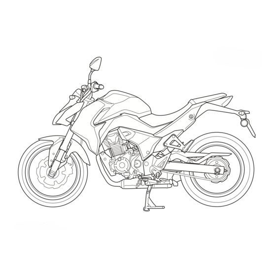
- Page 59 FRAME & CHASSIS BODY PANELS FRAME & CHASSIS [10] [17] [11] [16] [15] [13] [12] [14] [1] Rearview mirror 3-3 [10] Rear fender A 3-10 [2] Front visor 3-7 [11] Rear fender B 3-11 [3] Front fender 3-8 [12] Drive chain cover 3-11 [4] Fuel tank shroud 3-6 [13] Pillion step 3-4 [5] Brake pedal 3-13...
- Page 60 FRAME & CHASSIS REARVIEW MIRROR 34 N·m 34 N·m SEAT...
- Page 61 FRAME & CHASSIS SIDE COVER PILLION STEP...
- Page 62 FRAME & CHASSIS REAR COWL 1.0 N·m • Seat 3-3 • Side cover 3-4 • Pillion step 3-4 1.0 N·m...
- Page 63 FRAME & CHASSIS FUEL TANK SHROUD • Rear cowl 3-5 1.0 N·m...
- Page 64 FRAME & CHASSIS FUEL TANK CENTER COVER • Fuel tank shroud 3-6 FRONT VISOR • Speedometer 4-34...
- Page 65 FRAME & CHASSIS FRONT FENDER Except CL type • Front wheel 3-16 CL type • Front wheel 3-16...
- Page 66 FRAME & CHASSIS DRIVE SPROCKET COVER • Left side cover 3-4...
- Page 67 FRAME & CHASSIS REAR FENDER A 7.5 N·m 1.0 N·m • Rear cowl 3-5 1.0 N·m • Brake/tail light unit 4-28 3-10...
- Page 68 FRAME & CHASSIS REAR FENDER B • Rear fender A 3-10 DRIVE CHAIN COVER 3-11...
- Page 69 FRAME & CHASSIS BATTERY BOX 7.0 N·m • ECM 4-19 • Battery 4-28 STEP HOLDER 12 N·m • Side cover 3-4 3-12...
- Page 70 FRAME & CHASSIS BRAKE PEDAL • Step holder 3-12 GEARSHIFT PEDAL 3-13...
-
Page 71: Centerstand
FRAME & CHASSIS CENTERSTAND • Muffler cover 3-15 SIDESTAND 10 N·m 39 N·m 3-14... -
Page 72: Exhaust Pipe/Muffler
FRAME & CHASSIS EXHAUST PIPE/MUFFLER 20.5 – 22.5 mm 11 N·m 26 N·m 10 N·m 3-15... -
Page 73: Front Wheel
FRAME & CHASSIS FRONT WHEEL 64 N·m 23 N·m 3-16... - Page 74 FRAME & CHASSIS 42 N·m Install the bearing according to the number of the figure. • Install the bearing remover head into the bearing. From the opposite side, install the bearing remover shaft and drive out the bearing from the wheel hub. Remover head, 15 mm: 07746-0050400 Bearing remover shaft: 07746-0050100 •...
-
Page 75: Fork
FRAME & CHASSIS FORK 33.5 mm 23 N·m 23 N·m • Handlebar 3-20 • Front fender 3-8 • Brake caliper 3-28 • Install the front fork so that the length from the top bridge surface is 33.5 mm. 3-18... - Page 76 FRAME & CHASSIS 70 mm 28 N·m Contact. 28 N·m • Drive in a new oil seal squarely until it is fully seated. Driver: 07749-0010000 Bearing installer: 070MF-MEN0100 • Pour the specified amount of recommended fork fluid into the outer tube. RECOMMENDED FORK FLUID: MX4# FORK FLUID CAPACITY: 395 cm3 •...
-
Page 77: Handlebar
FRAME & CHASSIS HANDLEBAR 12 N·m 23 N·m 2.5 N·m 1.0 N·m 1.0 N·m 5.9 N·m • Front brake master cylinder 3-27 • Rearview mirror 3-3 • Install the clutch lever bracket and holder with the "UP" mark facing up. Align the edge of the clutch lever bracket with the punch mark on the handlebar. -
Page 78: Steering Stem
FRAME & CHASSIS STEERING STEM TOP BRIDGE 74 N·m 23 N·m • Handlebar 3-20 • Front visor 3-7 3-21... - Page 79 FRAME & CHASSIS BOTTOM BRIDGE Multi-purpose extreme pressure grease NLGI #2 (ALVANIA EP2 manufactured by Shell, EXCELITE EP2 manufactured by KYODO YUSHI CO., LTD. or equivalent) (3 g minimum) • Fork 3-18 • STEERING STEM: [A] Steering stem socket wrench: 07916-3710101 •...
-
Page 80: Rear Wheel
FRAME & CHASSIS REAR WHEEL 88 N·m • Wheel inspection 3-23... - Page 81 FRAME & CHASSIS 42 N·m Install the bearing according to the number of the figure. 64 N·m • Install the bearing remover head into the bearing. From the opposite side, install the bearing remover shaft and drive out the bearing from the wheel hub. Remover head, 17 mm: 07746-0050500 Bearing remover shaft: 07746-0050100 •...
-
Page 82: Rear Suspension
FRAME & CHASSIS REAR SUSPENSION 44 N·m (1.0 g) (1.0 g) 54 N·m 44 N·m • Rear cowl 3-5 • Drive chain cover 3-11 • Rear wheel 3-23 3-25... -
Page 83: Front Brake
FRAME & CHASSIS 7.0 – 8.0 mm FRONT BRAKE BRAKE FLUID REPLACEMENT 1.5 N·m Front brake: Rear brake: 1.5 N·m Set line Upper line • Add the reservoir with brake fluid from a sealed container to the set line and upper line. RECOMMENDED BRAKE FLUID: DOT 3 or DOT 4 3-26... - Page 84 FRAME & CHASSIS BRAKE MASTER CYLINDER 12 N·m 34 N·m • Install the brake master cylinder and holder with the "UP" mark facing up. Align the edge of the master cylinder with the punch mark on the handlebar. 1.5 N·m Silicone grease (0.1 g) 1.0 N·m...
- Page 85 FRAME & CHASSIS BRAKE CALIPER BRAKE PAD REPLACEMENT 18 N·m 2.5 N·m 26 N·m • Install brake pads so that they are set on the brake caliper bracket and bracket pin. 34 N·m 26 N·m 3-28...
-
Page 86: Rear Brake
FRAME & CHASSIS 8.0 N·m Silicone grease Silicone grease (0.4 g minimum) Silicone grease (0.4 g minimum) • Brake caliper inspection REAR BRAKE BRAKE MASTER CYLINDER 34 N·m • Step holder 3-12 3-29... - Page 87 FRAME & CHASSIS 1.5 N·m 17 N·m 1.5 N·m Silicone grease (0.1 g) • Remove the snap ring using the special tool. Snap ring pliers: 07914-SA50001 • Master cylinder inspection BRAKE CALIPER BRAKE PAD REPLACEMENT Silicone grease 17 N·m 3-30...
- Page 88 FRAME & CHASSIS 34 N·m • Rear wheel 3-23 Silicone grease (0.4 g minimum) Silicone grease Silicone grease (0.4 g minimum) 5.4 N·m • Brake caliper inspection 3-31...
- Page 89 MEMO...
- Page 90 4. ELECTRICAL SYSTEM PGM-FI SYSTEM ······························· 4-2 LIGHTING SYSTEM ·························· 4-28 IGNITION SYSTEM ···························4-21 SPEEDOMETER ······························ 4-34 ELECTRICAL STARTER ····················4-23 ELECTRICAL COMPONENT ·············· 4-38 BATTERY/CHARGING SYSTEM ·········4-27...
- Page 91 ELECTRICAL SYSTEM ELECTRICAL SYSTEM PGM-FI SYSTEM • Refer to "Basic Shop manual" for the following information. – PGM-FI technical feature and each sensor function. – Symptom troubleshooting for the PGM-FI system. – MCS (Motorcycle Communication System) information. DTC CODE INDEX Function Failure Symptom/Fail-safe function Page...
- Page 92 ELECTRICAL SYSTEM PGM-FI SYSTEM LOCATION EOT SENSOR FUEL PUMP IGNITION SWITCH INJECTOR IACV BANK ANGLE SENSOR SENSOR CKP SENSOR SENSOR UNIT: · MAP SENSOR · IAT SENSOR · TP SENSOR...
- Page 93 ELECTRICAL SYSTEM PGM-FI SYSTEM DIAGRAM R/Bl Bl/W Bl/R Bl/R IGNITION SWITCH ENGINE STOP SWITCH BATTERY Br/Bu Br/Bu Br/Bu (33-2) Bl/R Br/Bu Bl/R (54-1,54-2) R/Bu FUEL PUMP Br/R BANK ANGLE SENSOR (12-1) P/Bl INJECTOR SENSOR UNIT (1-1,1-2) Bl/R Lg/Y SCS CONNECTOR MAP SENSOR (8-1,8-2) K-LINE...
- Page 94 ELECTRICAL SYSTEM DTC TROUBLESHOOTING DTC 1-1 (MAP SENSOR LOW VOLTAGE) • Fuel tank shroud 3-6 MAP Sensor Diagram Sensor unit 5P connector ECM 33P connector Lg/Y Lg/Y Sensor unit Lg/Y (MAP sensor) 1. MAP Sensor System Inspection • Check the MAP sensor voltage with MCS. •...
- Page 95 ELECTRICAL SYSTEM DTC 1-2 (MAP SENSOR HIGH VOLTAGE) • Fuel tank shroud 3-6 MAP Sensor Diagram Sensor unit 5P connector ECM 33P connector Lg/Y Lg/Y Sensor unit Lg/Y (MAP sensor) 1. MAP Sensor System Inspection • Check the MAP sensor voltage with MCS. •...
- Page 96 ELECTRICAL SYSTEM DTC 7-1 (EOT SENSOR LOW VOLTAGE) • Fuel tank shroud 3-6 EOT Sensor Diagram EOT sensor 2P connector ECM 33P connector Y/Bu Y/Bu Y/Bu EOT sensor 1. EOT Sensor System Inspection • Check the EOT sensor voltage with MCS. •...
- Page 97 ELECTRICAL SYSTEM DTC 7-2 (EOT SENSOR HIGH VOLTAGE) • Fuel tank shroud 3-6 EOT Sensor Diagram EOT sensor 2P connector ECM 33P connector Y/Bu Y/Bu Y/Bu EOT sensor 1. EOT Sensor System Inspection • Check the EOT sensor voltage with MCS. •...
- Page 98 ELECTRICAL SYSTEM DTC 8-1 (TP SENSOR LOW VOLTAGE) • Fuel tank shroud 3-6 TP Sensor Diagram Sensor unit 5P connector ECM 33P connector Sensor unit (TP sensor) 1. TP Sensor System Inspection • Check the TP sensor voltage with MCS. •...
- Page 99 ELECTRICAL SYSTEM DTC 8-2 (TP SENSOR HIGH VOLTAGE) • Fuel tank shroud 3-6 TP Sensor Diagram Sensor unit 5P connector ECM 33P connector Sensor unit (TP sensor) 1. TP Sensor System Inspection • Check the TP sensor voltage with MCS. •...
- Page 100 ELECTRICAL SYSTEM DTC 9-1 (IAT SENSOR LOW VOLTAGE) • Fuel tank shroud 3-6 IAT Sensor Diagram Sensor unit 5P connector ECM 33P connector Gr/Bu Gr/Bu Gr/Bu Sensor unit (IAT sensor) 1. IAT Sensor System Inspection • Check the IAT sensor voltage with MCS. •...
- Page 101 ELECTRICAL SYSTEM DTC 9-2 (IAT SENSOR HIGH VOLTAGE) • Fuel tank shroud 3-6 IAT Sensor Diagram Sensor unit 5P connector ECM 33P connector Gr/Bu Gr/Bu Gr/Bu Sensor unit (IAT sensor) 1. IAT Sensor System Inspection • Check the IAT sensor voltage with MCS. •...
- Page 102 ELECTRICAL SYSTEM DTC 12-1 (INJECTOR) • Fuel tank shroud 3-6 Injector Diagram ECM 33P connector Injector 2P connector Injector 2P connector (Wire side) (Injector side) P/Bl Br/Bu P/Bl From Battery Br/Bu Injector P/Bl 1. Fuel Injector System Inspection • Check the fuel injector with MCS. •...
- Page 103 ELECTRICAL SYSTEM DTC 21-1 (O SENSOR) • Fuel tank shroud 3-6 Sensor Diagram sensor 2P connector ECM 33P connector Bl/W Bl/W Bl/W sensor 1. O Sensor System Inspection • Test-ride the vehicle and check the O sensor with • Intermittent failure MCS.
- Page 104 ELECTRICAL SYSTEM DTC 29-1 (IACV) • Fuel tank shroud 3-6 IACV Diagram IACV 4P connector ECM 33P connector IACV 4P connector (Wire side) (IACV side) Br/W Bu/W Br/W Bl/Y Bu/W Bu/Bl Bl/Y Bu/Bl Bu/W IACV1A Bu/Bl IACV1B IACV Br/W IACV2A Bl/Y IACV2B 1.
- Page 105 ELECTRICAL SYSTEM DTC 33-2 (EEPROM) 1. EEPROM System Inspection • Check the EEPROM with MCS. • Intermittent failure • Is the DTC 33-2 is indicated? ► • Loose or poor contact at the connector Yes ▼ • Replace the ECM with a new one. 4-19, and re- check.
- Page 106 ELECTRICAL SYSTEM DTC 54-1 (BANK ANGLE SENSOR LOW VOLTAGE) • Fuel tank shroud 3-6 Bank Angle Sensor Diagram ECM 33P connector Bank angle sensor 2P connector R/Bu Bl/R R/Bu From Battery Bl/R Bank angle sensor R/Bu 1. Bank Angle Sensor System Inspection •...
- Page 107 ELECTRICAL SYSTEM DTC 54-2 (BANK ANGLE SENSOR HIGH VOLTAGE) • Bank angle sensor (Connector is connected.) 4-20 Bank Angle Sensor Diagram ECM 33P connector Bank angle sensor 2P connector R/Bu R/Bu Bl/R From Battery Bl/R Bank angle sensor R/Bu 1. Bank Angle Sensor System Inspection •...
- Page 108 ELECTRICAL SYSTEM • Fuel tank shroud 3-6 • ECM power circuit and ground circuit inspection EOT SENSOR 15 N·m • Side cover 3-4 • Engine oil 2-14 • EOT sensor inspection 4-19...
- Page 109 ELECTRICAL SYSTEM SENSOR 25 N·m • Fuel tank shroud 3-6 • Remove the O sensor. Flare nut socket: FRXM17 (Snap on) or equivalent BANK ANGLE SENSOR 10 N·m • Fuel tank shroud 3-6 • Bank angle sensor inspection 4-20...
- Page 110 ELECTRICAL SYSTEM IGNITION SYSTEM IGNITION SYSTEM LOCATION IGNITION SWITCH IGNITION COIL MAIN FUSE 20 A SPARK PLUG FUSE BOX: · FI 10 A CKP SENSOR BATTERY IGNITION SYSTEM DIAGRAM IGNITION FI 10 A MAIN 20 A SWITCH R/Bl Bl/W Bl/R ENGINE STOP SWITCH...
- Page 111 ELECTRICAL SYSTEM SPARK PLUG REPLACEMENT • Spark plug inspection. • Discard the spark plug in a accordance with the mainte- nance schedule. 1-23 16 N·m INSPECTION IGNITION COIL PRIMARY PEAK VOLTAGE • Refer to "Basic Shop Manual" for the detail information of ignition coil primary peak voltage inspection.
- Page 112 ELECTRICAL SYSTEM ELECTRICAL STARTER ELECTRICAL STARTER SYSTEM LOCATION STARTER SWITCH IGNITION SWITCH CLUTCH SWITCH MAIN FUSE 20 A STARTER RELAY SWITCH STARTER MOTOR NEUTRAL SWITCH BATTERY FUSE BOX: · FI 10 A ELECTRICAL STARTER SYSTEM DIAGRAM IGNITION SWITCH FI 10 A R/Bl Bl/W STARTER...
- Page 113 ELECTRICAL SYSTEM ELECTRICAL STARTER TROUBLESHOOTING STARTER MOTOR DOES NOT TURN • Fuel tank shroud 3-6 • Loose or poor contacts of related terminal/connector • Battery condition • Burned fuse Connector Diagram Starter relay switch 4P connector 1. Starter Relay Coil Input Circuit Inspection •...
- Page 114 ELECTRICAL SYSTEM STARTER MOTOR • Electric starter inspection 4-25...
- Page 115 ELECTRICAL SYSTEM NEUTRAL SWITCH • Drive sprocket cover 3-9 • Engine oil 2-14 4-26...
- Page 116 ELECTRICAL SYSTEM BATTERY/CHARGING SYSTEM BATTERY/CHARGING SYSTEM LOCATION REGULATOR/RECTIFIER MAIN FUSE 20 A ALTERNATOR BATTERY BATTERY/CHARGING SYSTEM DIAGRAM MAIN 20 A BATTERY REGULATOR/RECTIFIER ALTERNATOR • Battery/charging system information, troubleshooting and inspection 4-27...
- Page 117 ELECTRICAL SYSTEM BATTERY 9.0 N·m • Left side cover 3-4 LIGHTING SYSTEM 7.5 N·m 1.0 N·m • When LEDs headlight flickering, replace the regulator/rectifier with a known good one, and recheck. If the headlight still flickering, replace the headlight unit. •...
- Page 118 ELECTRICAL SYSTEM • Rear fender A 3-10 19 N·m • Front – Front visor 3-7 • Rear – Seat 3-3 4-29...
- Page 119 ELECTRICAL SYSTEM 1.0 N·m • Seat 3-3 HEADLIGHT AIM Beam Beam down 4-30...
- Page 120 ELECTRICAL SYSTEM TURN SIGNAL LIGHT TROUBLESHOOTING • When all turn signal lights blink faster than usual, replace the turn signal light relay with a known good one, and recheck. ALL TURN SIGNAL LIGHTS DO NOT LIGHT • Fuel tank shroud 3-6 •...
- Page 121 ELECTRICAL SYSTEM HANDLEBAR SWITCH LED TROUBLESHOOTING • Do not connect the battery to the handlebar switch LED directly to avoid damaging to the LED. • When part of the LED on the right or the left of the handlebar switch does not light, replace the handlebar switch with a known good one 3-20, and recheck.
- Page 122 ELECTRICAL SYSTEM IT DOES NOT LIGHT UP ALL OF THE LED ON THE RIGHT AND THE LEFT OF THE HANDLEBAR SWITCH • Speedometer (Connector connected) 4-34 • Loose or poor contacts of related terminal/connector • Battery condition • Burned fuse Speedometer 16P connector Br/Bl 1.
- Page 123 ELECTRICAL SYSTEM SPEEDOMETER 4-34...
- Page 124 ELECTRICAL SYSTEM CLOCK ADJUST • Push and hold both the SEL button and SET button for more than 2 seconds. • The clock will be set in the adjust mode with the hour dis- play flashing. 2 seconds • The time is advanced by one hour, each time the button is pushed.
- Page 125 ELECTRICAL SYSTEM VS SENSOR FUEL LEVEL SENSOR • Fuel pump unit 2-4 • Route the fuel level sensor wires to the guide and terminals properly. 4-36...
- Page 126 ELECTRICAL SYSTEM FUEL METER TROUBLESHOOTING FUEL METER NEEDLE DOES NOT MOVE • Fuel pump unit 2-4 • Loose or poor contacts of related terminal/connector Open circuit indication FULL Short circuit indication EMPTY 1. Fuel Level Sensor Circuit Inspection • Check the Y/W and G wire. •...
- Page 127 ELECTRICAL SYSTEM ELECTRICAL COMPONENT IGNITION SWITCH • Fuel tank center cover 3-7 HORN • Fuel tank shroud 3-6 4-38...
- Page 128 INDEX dummytext INDEX A Few Words About Safety······································1-2 FUEL PUMP UNIT·················································2-4 AIR CLEANER······················································2-7 FUEL TANK ·························································2-6 ALTERNATOR/STARTER CLUTCH························ 2-25 HANDLEBAR ····················································· 3-20 BATTERY/CHARGING SYSTEM···························· 4-27 HORN······························································· 4-38 BODY PANELS ····················································3-2 How To Use This Manual ········································1-3 BRAKE FLUID REPLACEMENT····························· 3-26 IGNITION SYSTEM ·············································...
- Page 129 CBF190WH-G (AC,CO,LA,CL,PE) STARTER MOTOR FUSE BOX BANK FUSE3 FUSE2 FUSE1 ANGLE SENSOR SENSOR METER UNIT IGNITION REAR MAIN SWITCH BRAKE FUSE LIGHT SWITCH STARTER RELAY BATTERY IACV SWITCH DIODE FRONT BRAKE LIGHT SWITCH Br/Bl Br/Bl MARK IND STARTER SWITCH Bu/W ENGINE Bl/R Bl/R...
- Page 130 © Honda Motor Co.,Ltd. 2016 Book#: 62K70M0 Published by Honda Motor Co.,Ltd. A. 2016.03 Printed in Japan...
Need help?
Do you have a question about the CBF190WH 2016 and is the answer not in the manual?
Questions and answers