
Related Manuals for Teradek LINK Pro

Summary of Contents for Teradek LINK Pro
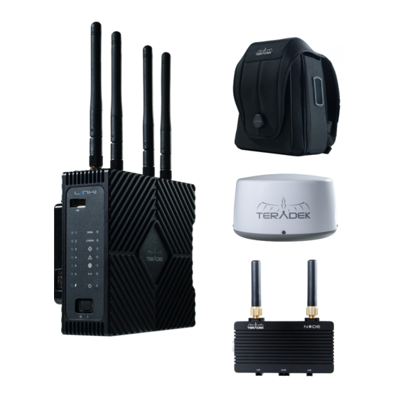
- Page 1 LINK PRO SYSTEM USER GUIDE © 2018 Teradek, LLC. All rights reserved. © 2018 Teradek, LLC. All rights reserved.
-
Page 2: Table Of Contents
TABLE OF CONTENTS Physical Properties ..........3 Getting Started ............5 Connect to a Network ........5 Node ...............6 Connect Nodes to Link Pro ......6 Bonding Configuration ........7 Network Configuration ........8 Link Pro Backpack ..........9 Link Pro Radome ..........10 Technical Specifications ....... 11 Support Resources ......... -
Page 4: Physical Properties
SMA connectors Power indicator Network indicator SIM card slot 4-40 threaded mount 1/4"-20 threaded mount Teradek regularly releases new firmware versions to improve performance, add new features, or to fix vulnerabilities. Visit https://www.teradek.com to update your device with the latest firmware. -
Page 5: F: Node Assembly
4-pin data/power input 3 SIM card slot 4 4-pin data/power input 4 NEED MORE HELP? Support: http://support.teradek.com → Contains tips, information and all the latest firmware & software updates. TERADEK SUPPORT STAFF: support@teradek.com or call 888−941−2111 ext2 (Mon−Fri 6am to 6pm PST) -
Page 6: Getting Started
(Gold or V mount). Reset button If necessary, you can restore Link Pro to its original settings button (L), then by inserting a paper clip into the recessed holding it down for five seconds. -
Page 7: Node
Remove the SIM cover plate and insert a SIM card into the slot of each Node. Replace the cover plate and screw. Connect Node(s) to Link Pro using the included 18” 4-pin to 4-pin cables. Node’s power LEDs should illuminate immediately. The network LEDs will also illuminate once an Internet connection is established. -
Page 8: Bonding Configuration
BONDING CONFIGURATION After connecting to the device’s web UI, Link Pro needs to be connected to a Core account with an active Hotspot subscription. Connecting Link Pro to Hotspot increases your bandwidth and reliability by bonding multiple Internet connections. To take advantage of these features, visit hotspot.teradek.com and sign up for a Hotspot subscription, or sign up from your existing Core account by selecting a subscription plan from the Manage Account page. -
Page 9: Network Configuration
Link Pro to another network. These settings do not need to be modified if Link Pro is used as a stand-alone access point. When connecting Link Pro to another network with an existing DHCP server, uncheck the box next to ‘Enable DHCP... -
Page 10: Link Pro Backpack
V mount) to the battery plate. Turn the front power switch to the On position. Teradek regularly releases new firmware versions to improve performance, add new features, or to fix vulnerabilities. Visit https://www.teradek.com to update your device with the latest firmware. -
Page 11: Link Pro Radome
Link-Pro-XXXXX 5G (XXXXX is the last five digits of the device’s serial number). NEED MORE HELP? Support: http://support.teradek.com → Contains tips, information and all the latest firmware & software updates. TERADEK SUPPORT STAFF: support@teradek.com or call 888−941−2111 ext2 (Mon−Fri 6am to 6pm PST) -
Page 12: Technical Specifications
TECHNICAL SPECIFICATIONS Link Pro PROTOCOL SUPPORT Network Protocols TCP/IP, UDP, HTTP, DHCP, NTP, SSL, IGMP Bonding Up to 6 Devices, Ethernet Remote Teradek Core PHYSICAL ATTRIBUTES Dimensions 1.69”W x 5.22” D x 4.72 H” [43 x 132.6 x 120 mm] Weight 19.8 0z. - Page 13 Node PHYSICAL ATTRIBUTES Dimensions 1.69”W x 5.22” D x 4.72 H” [43 x 132.6 x 120 mm] Weight 19.8 0z. (560 g) Construction Milled Aluminum NETWORK US: LTE FDD Cat 4, Bands 2,4,5,13,17 EU/Asia: LTE FDD Cat 4, Bands 1,3,5,7,8,20 JP: LTE FDD Cat 4, Bands 1,3,5,8,19 SA/AUS: LTE FDD Cat 4, Bands 1,3,5,7,8,28 US: HSDPA Cat 24, HSUPA Cat 6, Bands 850/1900...
-
Page 14: Support Resources
In addition to this User Guide, there are a number of resources available with information on Link Pro’s features and operation. For online information, visit www.teradek.com. If you are unable to find what you need online, please contact Teradek’s support staff: E-mail: support@teradek.com | Phone: (888) 941-2111 ext.
Need help?
Do you have a question about the LINK Pro and is the answer not in the manual?
Questions and answers