Advertisement
Advertisement
Table of Contents

Related Manuals for MERQUIP NIAGARA


Summary of Contents for MERQUIP NIAGARA
- Page 1 NIAGARA Installation, use and maintenance handbook COD: 5561397 Rev.0:0210...
- Page 2 APPLIANCE DATA PLATE MANUFACTURER Model Supply voltage WATER COOLERS Quantity of cooling gas Mod....Class Total absorption ..V ..Hz ..W ..A Frequency Serial number Freon R134a kg..... Classe T Construction year-month MADE IN ITALY 000100 0102 CONFORMANCE STATEMENT This appliance has been manu- factured with suitable materials for use with drinking water.
-
Page 3: Before Using The Appliance
BEFORE USING THE APPLIANCE Failure to comply with any of these safety regulations could machine, disconnect it immediately from the socket and contact the local cause fires, electric shocks or damage the machine retailer or technical service assistance. Use of the machine in these conditions could cause fires or electric shocks. -
Page 4: Removal Of Packaging
REMOVAL OF PACKAGING Information: This appliance does not contain CFCs (the cooling circuit • Place the appliance in its installation site (chap. 5 - INSTALLATION). contains a gas that is not harmful to the ozone layer). • Cut straps R and remove carton C, polystyrene F and external plastic bag S. •... -
Page 5: Description Of The Appliance
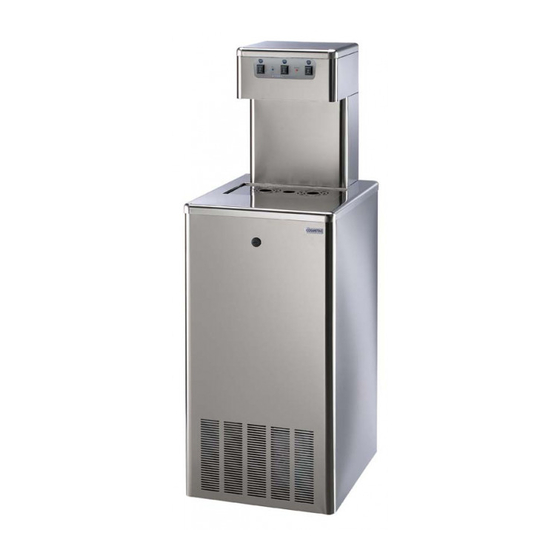
DESCRIPTION OF THE APPLIANCE These water coolers were designed to provide large quantities of still and They are equipped with an internal cooling system, capable of supplying carbonated cold water. water cooled to 3 ÷ 10°C. They are easy to use and manufactured using top quality materials, offering They use a direct cooling system (ice bank) the utmost hygiene and ease of maintenance;... - Page 6 GENERAL VIEW FREE STANDING MODELS Structure Distribution nozzle positioned in a protected area Front panel 10) Mains water inlet ø 8mm (or 3/4 M ) Panel fastening 11) Power supply cable Tray grille 12) Drain water (ø 24mm) and overflow ice compartment Column 13) Removable panel for compressor maintenance 14) Adjustable levelling feet...
- Page 7 A C Q IC O C A R A N K L IC F IL COUNTERTOP MODELS (TOP) UNDERCOUNTER MODELS (IN) Cold water thermostat Cold water thermostat Electrical power supply socket Electrical power supply socket Main switch Main switch Mains water inlet ø 8mm or 3/4 M Mains water inlet ø...
-
Page 8: Technical Characteristics
NIAGARA SL Dimensions (mm) 65 SL 65 SLWG 120 SL 120 SLWG 180 SL 180 SLWG 1480 1480 IN 65 IN 120 TIN 180 NIAGARA IN IN 65 WG IN 120 WG IN 180 WG NIAGARA TOP TOP 65 TOP 120... - Page 9 NIAGARA SL NIAGARA TOP NIAGARA IN WG 120 WG 120 Lt/h Water production usg/h 47,5 47,5 17,2 17,2 31,7 31,7 47,5 47,5 17,2 17,2 31,7 31,7 47,5 47,5 17,2 17,2 31,7 31,7 3 ÷ 10 °C Water outlet temperature 38 ÷50 °F...
-
Page 10: Installation
NI1404-F01 INSTALLATION POSITIONING THE APPLIANCE Position the appliance in the point of installation, away from sources of heat and direct sunlight. The appliance is not suitable for outdoor use and it is also not recommended to install it in very damp rooms. - Adjust the feet in ground models (1) to make the structure level (fig.7). - Page 11 NI1404-110 NI1404-100 NI1404-090 INSTALLATION WATER CONNECTION TO THE MAINS N.B.: the pressure is especially important for those water coolers fitted with a carbonation device. During connection of the appliance to the mains water supply, Attention! All models are equipped with a water pressure reducer all pre-existing tubes, gaskets and joints placed between the calibrated at 3 bar, installed on the machine on ground models and appliance and the water mains connection must be replaced...
-
Page 12: Electricity Connection
NI1404-F12 NI1404-030 NI1404-180 16.1 • On models IN and TOP the clean water drainage pipe of the ice bank 13 disconnected. (if present) must be connected to a siphoned drain. If necessary cut the • If you need to unfasten pipe T (fig. 13): - press onto the locking ring using an ø... - Page 13 NI1404-120 18.1 COLDER IN WATER IN CO2 FILL ICE BANK STARTING CONNECTION TO THE CO2 CYLINDER (WG models) Warning! If the appliance has been laid down or turned upside For the production of carbonated water, you must provide a CO cylinder down, you should wait at least 8 hours before starting it.
- Page 14 NI1404-130 cylinder capacity 4 Kg (8,8 Ibs) 10 Kg (22 Ibs) cylinder charging range 1600 184,1 420,8 SETTING UP THE SPARKLING WATER NOTICE CAUTION! AFTER TRANSPORTING, STORING AND USING CO CYLINDERS, FOLLOW LOCAL REGULATIONS CONCERNING THEIR USE. 1) CO cylinder 2) CO cylinder tap •...
- Page 15 Attention : to carry out this or any other maintenance operation requiring the machine casing to be opened, use protective gloves to avoid being cut by the sharp edges of the sheet steel Advice on using the appliance for carbonated water carbonation device.
-
Page 16: Routine Maintenance
21.1 Maintenance operations should be carried out by a qualified 21.2 professional. Be careful also not to damage the refrigerator system circuit. ROUTINE MAINTENANCE Cleaning the outside - Clean the external part with a damp cloth, do not use solvents or abrasive deter- of the appliance gents CO2 cylinder... - Page 17 NI1404-F0004 22.1 ROUTINE MAINTENANCE Power supply cable - Check the condition and soundness of the electricity supply cable. Every month Hydraulic connection - Check the condition and soundness of the water supply pipe and that the drain pipe is in good order. Every month control - Make sure there are no leaks.
-
Page 18: Faults And Remedies
INTERNAL CLEANING/ HYGIENIC CLEANING WARNING! Considering that the products used for the hygienic cleaning are acid and alkali corrosive substances, disposable gloves must be used as well as glasses to protect your eyes. When this hygienic cleaning is carried out, you must keep to the product reaction times, percentages of hygienic detergent and quantity of water necessary for rinsing. -
Page 19: Cooling System
COOLING SYSTEM ANOMALY POSSIBLE CAUSE INTERVENTION Ithe compressor will - power failure - check that there is voltage in the plug not start - thermostat on the off position, or set to the mi- - adjust the thermostat position nimum - faulty thermostat - replace the thermosta - the over-load protection of the compressor is faulty... - Page 20 MERQUIP LTD NZ DISTRIBUTORS 58 Walls Road, Penrose,Auckland 1061 PO Box 13-927 Onehunga, Auckland 1643 Free Phone: 0800 636 0 636 T: 09 636 0 636 F: 09 636 8 636 E: info@merquip.co.nz www.merquip.co.nz...
Need help?
Do you have a question about the NIAGARA and is the answer not in the manual?
Questions and answers
I Would like to install one water machine in our hotel cam you please us. Thanks
To install a MERQUIP Niagara water machine in a hotel, follow these steps:
1. Placement:
- Ensure the machine is placed flat and resting on all four feet.
- Leave approximately 10 cm of free space around it for air circulation.
- The condenser side must be easily accessible for cleaning.
2. Ventilation:
- For undercounter models, provide ventilation grills or slits (recommended 300x300 mm) to allow heat from the refrigerating circuit to escape.
3. Water Connection:
- Connect the machine to the mains water supply.
- Replace all pre-existing tubes, gaskets, and joints between the appliance and the water mains.
- The machine includes a water pressure reducer calibrated at 3 bar (important for models with carbonation).
4. Electrical Connection:
- Insert the plug firmly into a wall socket, not shared with other equipment (no extensions or adaptors).
- Do not connect or disconnect with wet hands and avoid damaging or placing heavy objects on the power cable.
5. Cleaning and Safety:
- Do not use flammable solvents for cleaning.
- Never use water jets; clean with a damp cloth.
- Turn off and unplug the machine before cleaning.
6. Environmental Considerations:
- Dispose of packaging materials properly and avoid installing in very damp rooms.
- The appliance does not contain harmful CFCs and is marked under the WEEE directive.
This answer is automatically generated