Table of Contents
Advertisement
Quick Links
INSTALLATION
®
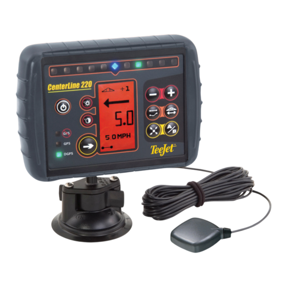
The CenterLine
220 is equipped with three cables: the attached
Power/GPS Speed cable, the Antenna cable, and the Power Adapter
cable.
POwEr/GPS SPEED CABLE - The CL220 should be connected
to a clean cigarette lighter receptacle for power. As an option, the
CL220 can be connected to any controller or monitor that supports a
radar speed input. when connected to the radar speed input of the
monitor or controller, the CL220 will be powered by the controller and
will provide a radar-like speed signal to that device.
GPS ANTENNA AND CABLE - The antenna is magnetic, so for metal
vehicles, position the antenna in the center of the vehicle at the high-
est point. For non-metal vehicles, a metal plate with adhesive strips
has been included in the kit for easy mounting and installation. It is
STrONGLY recommended to use this metal plate underneath the
antenna as it will also boost signal strength. Once the antenna has
been positioned, route the antenna cable carefully to avoid damage.
Attach it to the threaded connector on the back of the CL220.
GPS Antenna
Antenna Mounting
Plate
65-05179
Vecro
Strips
TM
60-10081
45-05478 Cable, Battery Power
Power Cable
45-05478
45-05471 Cable, Adapter Weather-Pack
Speed/Power
POW ER CABLE
45-054 71
Cable
DC: XXXX
GPS Speed/Power Cable
*45-05458 Cable, Lighter Adapter
Power Cable
Connect to
45-05458
+12v Only
DC:xx/xx/xx
- Connect to cigarette lighter
*included in kit 90-02399
with the power adapter cable.
or
- Connect directly to radar speed
Press suction cup to mounting surface and ro-
input of a compatible controller
tate locking arms clockwise to the ON position.
(refer to CL220 Providing Speed Signal
on reverse)
Position the GPS antenna in the center
of the vehicle at the highest point with
a clear view of the sky. If the tractor is
non-metal, mount the metal plate in the
center of the vehicle at the highest point
with the adhesive strips and place the
antenna on the plate. route the antenna
cable carefully to avoid damage.
Antenna
Lightbar
Power
10
Brightness
4
9 .
Contrast
GPS
5.8 MPH
GPS Status
GPS
Lights
DGPS
Change
Display
Page
CENTErLINE 220 SETUP AND OPErATIONS
Press the Power
button to power up the CL220. The CL220 start-
up screen will appear until a GPS signal is acquired. Press the Power
button again to power down the console.
BrIGhTNESS/CONTrAST
Press the Brightness
Use the Increase and Decrease
to make adjustments. To invert the colors on the
display, press and hold the Contrast
3 seconds.
SwATh wIDTh
+12v Only
Press the Swath width
crease and Decrease
justments to the swath width.
The swath width value is displayed in feet. The
swath width measurement displayed will be used
until changed.
SETTING ThE INITIAL GUIDELINE
At the desired location for guidance to begin,
press the Mark A-B
A
marked. The display will then change to Mark B.
Travel to the location for Point B to be marked.
Metal plate
Press the Mark A-B
The CL220 will begin providing guidance with the
lightbar and data display.
Increase/
Decrease
Guidance
GPS
Mode
GPS
Swath width
DGPS
return to
Mark A/B
Point
SETTING INITIAL GUIDELINE (CONTINUED)
If the Mark A button was pressed inadvertently
and a Point A was created, it can be released by
pressing the Mark A-B
B
Decrease
or Contrast
buttons.
buttons
button for
GUIDANCE MODE
Press the Guidance Mode
or Curved A-B Guidance. View the bottom left of the
display window to see the Guidance mode selected.
guidance mode selected
STrAIGhT A-B MODE
guidance between two reference points (Points A
and B).
button. Use the In-
buttons to make ad-
CUrVED A/B MODE
between two reference points (Points A and B). All
swaths are identical to the path driven on the first
pass between Points A and B.
Straight A-B Guidance
Curved A-B Guidance
B
Point
A
Point
button. Point A will be
Curved A-B Guidance
Straight A-B Guidance
button to mark Point B.
A+ NUDGE FEATUrE
At any time after a guideline is created, the guidance line can be
shifted to the current vehicle position by pressing the Mark A-B
button followed by the Increase
if in Curved Guidance mode) of the original guideline is maintained,
but the A-B line is shifted to the vehicle's present location.
GPS
GPS
GPS
GPS
DGPS
DGPS
lights illuminated on the left of the
lightbar require a steering adjust-
ment to the right
ChANGE PAGE
button followed by the
button.
Data Page
button to select Straight
rETUrN TO POINT
provides straight line
provides curved guidance
The arrow points in
the direction of the
marked point
B
Point
A line is drawn between
the marked point and the
A
Point
Distance to point
button. The heading (and shape,
7.5 ft (2.3 m)
1.5 ft (.45 m)
4.5 ft (1.4 m)
3.0 ft (.9 m)
6.0 ft (1.8 m)
Center
lights illuminated on the right of the
lightbar require a steering adjust-
ment to the left
Use the Change Page
button to alternate be-
tween the Data Page and the Map Page.
Map Page
The dashed lines
represent
adjacent swaths
Press the return To Point
button to store a loca-
tion in which to return at a later time. A dot will ap-
pear on the bottom of the display, indicating that a
position has been stored.
To locate the point, press the return To Point
button again and begin navigating toward the point
as indicated on the display. To exit return To Point,
press the return To Point
button again. Use the
Change Page
button to switch between the re-
turn To Point display screens.
The vehicle is at the
marked point location
vehicle
Advertisement
Table of Contents

Related Manuals for TeeJet Technologies CL220


Summary of Contents for TeeJet Technologies CL220
- Page 1 As an option, the Point Page CL220 can be connected to any controller or monitor that supports a radar speed input. when connected to the radar speed input of the CENTErLINE 220 SETUP AND OPErATIONS monitor or controller, the CL220 will be powered by the controller and will provide a radar-like speed signal to that device.
- Page 2 CUrVED A-B MODE DETAILED DESCrIPTION CENTErLINE 220 PrOVIDING SPEED SIGNAL The CL220 can be connected to any controller or monitor that sup- Curved A-B mode provides curved guidance between two refer- ports radar speed input. when connected to the radar speed input of ence points - Points A and B.
Need help?
Do you have a question about the CL220 and is the answer not in the manual?
Questions and answers