
Related Manuals for CompAir DELCOS Pro


Summary of Contents for CompAir DELCOS Pro
- Page 1 Original User Manual DELCOS Pro electronics for stationary rotary screw compressor Id. no. 100013596 / 03 - January 2010...
- Page 3 German basis BA 100013595/03 Valid as of software version DPro-L-1.xx We reserve the right to modifications relating to technical advances.
-
Page 4: Table Of Contents
5.5 [OPTIONAL IN-/OUTPUTS] sub-menu ........................15 5.5.1 Inputs ................................15 5.5.2 Outputs ................................16 5.6 Locking / unlocking code ............................16 5.7 Replacing the DELCOS Pro (SETUP-CODE)......................17 5.8 Remote control................................18 5.8.1 Remote control for pressure changeover ......................18 5.8.2 On-load/off-load remote control ........................19 5.8.3 Remote start / stop............................20 6 Error rectification................................21... -
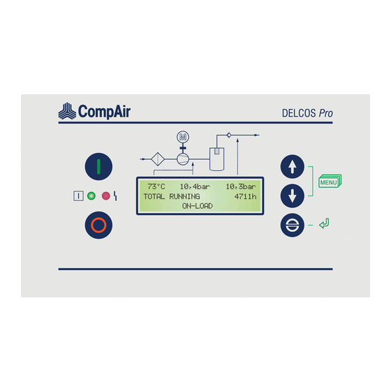
Page 5: Operator Controls / Arrangement
Switch to next sub-menu / menu item, messages. or reduce a value Light signals The DELCOS Pro is fitted with two light signals (red, Switch to previous sub-menu / menu item, green). or increase a value... -
Page 6: Status Messages In Display
1. Operator controls / arrangement 1.2.1 Status messages in display WARNING START IN The status messages are shown in the 3rd row of the alternating with display. With longer texts, the indication may 'alternate'..AFTER DRYER PRE-RUN Status messages: The unit has been switched on and is ready. -
Page 7: Menu Structure (Values Are Examples)
1. Operator controls / arrangement Menu structure (values are examples) + TOTAL RUNNING 12345h [MAINTENANCE SCHED.] LOADED HOURS 10987h + AIR FILTER IN 2000h OIL FILTER IN 2000h ... -
Page 8: Displaying / Changing Values
1. Operator controls / arrangement Displaying / changing values 1.4.1 Selecting values You can display values, e.g. total hours, and set the control system, e.g. cut-in and cut-out times, in the sub- menu. To reach the main menu, you must press the ... -
Page 9: Default Settings
- have to be pressed at the same time to do this. You are The DELCOS Pro accumulator can bridge a loss of then taken to the main menu. Use to switch to the power lasting between around two to three weeks. If ... -
Page 10: Operations
The emergency off button is located above the ON-LOAD: DELCOS Pro. It is used to immediately shut down the unit. Only use the emergency off button to shut down If the unit is in ON-LOAD, air is pumped into the the unit in emergencies. -
Page 11: Maintenance ([Maintenance Sched.] Sub-Menu)
The total hours counter states the time for which your conditions. unit has been in on-load and off-load. The DELCOS Pro allows the operator to program The load hours counter states the time for which your various maintenance intervals (see section 4.2). -
Page 12: Extended Functions
5.1.2 Second pressure range (p The DELCOS Pro has a serial RS485 interface. This The range between the maximum and minimum interface can be used with the ModBus RTU protocol. network pressure is called the pressure range. The... -
Page 13: Automatic Re-Start
Always fit the compressor with warning signs, lock automatic re-start by entering a code. the room containing the compressor and instruct Please request the required code from the CompAir your staff. customer service. Fit the main switch specified by EN60204 and fit the appropriate warning signs on it. -
Page 14: Fault Memory ] Sub-Menu
5. Extended functions To access this information please use to go to [ FAULT MEMORY ] sub-menu the warning message or fault that you are interested in in the fault memory. Now press the key. The day of Warning messages and faults are stored in the fault memory. -
Page 15: Pressure Changeover Setting
5. Extended functions If there are no days of the week selected in the Example 3: switching unit line, the switching unit is not active. The The unit is to run from Sunday 10 pm through switching unit only becomes active when the day of the continuously to Saturday 2 pm. -
Page 16: Limit Values] Sub-Menu
5. Extended functions Seven timer units are again available here for the [Limit values] sub-menu setting (programming). The values that you have set for the second pressure range supersede the values for The [ LIMIT VALUES ] sub-menu is for information CUT-OUT POINT and CUT-IN POINT as soon as a only. -
Page 17: Optional In-/Outputs] Sub-Menu
If the network pressure is ≥ 1.0 bar and the contact is opened for at least 250sec., BEKOMAT FAULT appears The DELCOS Pro has five programmable inputs. These on the display. This function results in the unit shutting inputs can be assigned (programmed) various down. -
Page 18: Outputs
240V. The output (relay) is activated when there are no warnings, no maintenance messages and no faults on The DELCOS Pro has two programmable outputs. the compressor. Output 1 is a relay with changeover contact and output 2 is a relay with NO contact. You can assign (program) REM.STARTABLE... -
Page 19: Replacing The Delcos Pro (Setup-Code)
The display then automatically jumps back to where it started from. Sticker Replacing the DELCOS Pro (SETUP- CODE) Once the new DELCOS Pro has been fitted in your compressor, switch the main switch back on. The following now appears on the display: COMPAIR SETUP-CODE 1: 0000 You will find the setup codes on a sticker (see Fig. -
Page 20: Remote Control
But you can also activate the second pressure range remotely. This is done using a digital input (input X in Fig. 5) on the DELCOS Pro (see section 5.5.1 and circuit diagram). In the [OPTIONAL IN-/OUTPUTS] menu you have to program the inputs using the 2nd PR. -
Page 21: On-Load/Off-Load Remote Control
(decoupled). If input 2 is now activated, the machine is control cabinet. in on-load. If input 2 is not activated, the machine is in The DELCOS Pro control system allows the operator to off-load. switch the compressor into on-load or off-load from a... -
Page 22: Remote Start / Stop
If the remote start / stop function is activated, you can no longer control the machine using the On keys on the DELCOS Pro. Only the emergency off button remains activated. The machine can now only be switched on and off using the potential-free contact. -
Page 23: Error Rectification
9. Do not connect up extra switching or measurement - Warning messages are shown in the 3rd display row. devices without the consent of CompAir. The red light signal on the DELCOS Pro also flashes 10. Do not route any measurement recorders out of the slowly. - Page 24 6. Error rectification [Indication] / Problem Possible cause Remedy Power loss Find cause FAULT POWER LOSS Voltage dip Find cause Cabling damaged Check, repair if necessary Loose terminals Check that all connecting terminals and plugs are tight, retighten if necessary FAULT EM-STOP Emergency off is being/has been activated Unlock...
- Page 25 Check dryer WARNING DRYER WARNING There is an external dryer error Check dryer FAULT DRYER FAULT DELCOS Pro hardware error Replace DELCOS Pro electronics FAULT DELCOS WARNING TIMER The real timer's accumulator is flat The real timer must be reset (see section 2.3).
- Page 26 6. Error rectification [Indication] / Problem Possible cause Remedy Unit runs continuously in off- CONTINUOUS OPERATION operating mode Select AUTOMATIC OPERATION load without independently selected operating mode switching to readiness (standby) Very brief pressure requirements during the run-on time No compressed air Pressure changeover by timer or requirements within the external contact active...
- Page 28 Gardner Denver Deutschland GmbH Argenthaler Str. 11 55469 Simmern Germany Tel. ++49 (0)6761 832-0 www.compair.com e-mail: sales@compair.com...
Need help?
Do you have a question about the DELCOS Pro and is the answer not in the manual?
Questions and answers