
Subscribe to Our Youtube Channel
Related Manuals for CompAir DELCOS XL Series


Summary of Contents for CompAir DELCOS XL Series
- Page 1 Translation of the original operating instructions Compressor controller DELCOS XL / DH-Series ZS1091756 / 01 - October 2013...
-
Page 2: Table Of Contents
Contents CONTENTS Start Inhibits..........40 Operations..........41 Foreword............3 Operating Modes........41 Water circuit control........ 41 About these operating instructions....3 Stopping the compressor......42 Intended use..........3 Operational monitoring......42 Intentional misuse........3 Service............3 Troubleshooting.......... 43 Troubleshooting check list...... 43 Safety conditions.......... 4 How the Fault and Warning Codes are Identification of safety instructions.... -
Page 3: Foreword
Foreword FOREWORD The operating instructions for the compressor must be observed in addition to these operating in- About these operating structions. instructions Intended use These operating instructions contain information The controller DELCOS XL installed is exclusively about controllers for fixed speed or variable speed intended for use with series DH compressors from compressors and water- or air-cooled compres- Gardner Denver. -
Page 4: Safety Conditions
Safety conditions SAFETY CONDITIONS DANGER WORD Gardner Denver Deutschland GmbH accepts no Danger (danger sequence) responsibility for material damage or injuries that Description of the danger (danger arise from non-observation of safety conditions or Safety sign source) the failure to observe normal levels of care and at- Protective measure (danger pre- tention, even where this is not expressly stated in vention) - Page 5 Safety conditions Safety sign Meaning Use / Behaviour Pressurised part or sys- Identification of devices or rooms in which there is per- manently or occasionally a significantly higher air pres- sure than in the normal atmosphere. Do not open the devices or rooms before pressure equalisation has taken place.
- Page 6 Safety conditions Safety sign Meaning Use / Behaviour Warning against moving During maintenance work it is necessary to check some machine parts functions with an opened enclosure. There is a risk of injury due to rotating or translational movements. Maintenance work must only be carried out by specially trained personnel.
- Page 7 Safety conditions Safety sign Meaning Use / Behaviour Safety valve Opening pressure of the safety valves (values "xx" see sticker on the control panel). XX bar Check the connecting Warning against loosened connecting terminals. The terminals and tighten if clamping pressure can be released after some time. necessary.
-
Page 8: Control Panel And Control
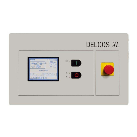
Control panel and control CONTROL PANEL AND Selection CONTROL If it is only possible to choose between fixed de- fined values for entry, the corresponding selection input menus are displayed. Control Operating Mode Continuous Operation Automatic Operation Fig. 3-1: Control panel Touchscreen display Start button <... - Page 9 Control panel and control Parameters Access Code If parameters must be entered, an appropriate soft keypad is displayed. Alongside the statement of Input Access Code the parameter that can be entered by the input, the possible adjustment range is displayed. Control Status: User Settings...
-
Page 10: Menus
Menus MENUS Menu Structure Home (1) Home Date and time / language selection Operating display (pictogram with measurement and setpoints) Status-/ message area Hours run / service hours Status switch on functions On-Load 0rpm Hours Run Remote Start Enabled Hours On-load Timer start enabled Hours to next Service Auto. - Page 11 Menus Home On-load 2600rpm Remote Start Enabled Hours Run Timer start enabled Hours On-load Auto. Restart Enabled Hours to next Service Fig. 4-2: Menu "Home" time and date Status-/ message area Direct access <"Language selection"> Status switch on functions Volume flow Tabs Network pressure Service information...
- Page 12 Menus "p1" is the normal pressure band that is used as Remote Start standard. Timer Control "p2" is a second pressure band that can be used AutomaticRestart if a different line pressure is required. The second pressure band can be switched to using the inte- [7.1] Status remote start grated timer control (see chapter "Timer control The status of the switch on functions is indicated...
- Page 13 Menus [9] Service information Symbol Name Description The following service information is displayed: Normal operating <Home> Operating hours display. Load hours Hours until the next maintenance is due Display of various <Trends> compressor sta- [9.1] Operating hours tistics or trends Display of the drive motor running hours.
-
Page 14: Pictogram
Menus Pictogram Fig. 4-4: Pictogram Air Filter Time until the next water change Airend Water level display Temperature outlet airend Pressure tank Pressure in the pressure vessel [10] Drive motor [11] Air delivery Drive motor speed markings (standstill, off- load, max.) (only for a speed-controlled compressor system) Pressure retaining and non-return valve... - Page 15 Menus This bar graph shows how many hours the RS Volume flow compressor has been operated with various vol- Trends ume flows. It also shows the average total volume flow since the last reset. Volume Flow Trends Statistics On-Load Hours Hours Run Hours On-load Average Volume Flow...
-
Page 16: Menu "Settings
Menus This graph shows the variation in the motor speed Menu "Settings" over a specified period. NOTE Contents of line graphs All specific settings should be recorded, so that X-axis; time axis if necessary they are available (e.g. for setting Y-axis;... - Page 17 Menus "p1 Cut-Out Point"; to configure the pressure Hour Meters band. See chapter "Configuration / Set pres- Hour Meters sure bands". "p1 Cut-In Point" (FS) / "p1 Target Select a Setting Hours Run Pressure" (RS); to configure the pressure band. See chapter "Configuration / Set pressure Hours On-load bands".
- Page 18 Menus The menu "Programmable Inputs and Outputs" is Timer Control used to allocate inputs and outputs. See chapter Timer Control "Configuration / Programming Inputs and Outputs" for details on configuring inputs and outputs. Select a Setting Date and Time Communication Timer Start/Stop Display / Adjust Communication...
- Page 19 Menus "Pressure Unit"; to set the pressure unit. See "Heavy Startup"; if the tank pressure reaches chapter "Configuration / Setting Measurement this value during the start phase, the compres- Units". sor is stopped. (compressor without speed con- trol) "Volume Flow Unit"; to set the volume flow rate.
-
Page 20: Menu "Fault History
Menus Water circuit control... Fault History Water circuit control Fault E419: Water level min. Select a Setting When 29.Jan.2013, 15:53:23 Replacement cycle Hours Run TotalCount Replacement remaining Status on-load 2700rpm Final pressure 7.7bar Final temperature 36°C Line pressure 7.5bar Water level Speed 2700rpm Heatsink Temperature 20°C... - Page 21 Menus Entering and using access codes 1 Tap the <Access Code> tab. – The input mask "Access Code" appears. 2 Tap the <Number buttons> to enter the appro- priate access code. 3 If necessary, make any corrections with the <Back> button. 4 Tap the <Enter>...
-
Page 22: Configuration
Configuration CONFIGURATION Choose Language Choose Language 1 Tap the <Globe Symbol> in the "Home" menu. – The menu "Choose Language" appears. Choose Language Fig. 5-2: Menu "Choose Language" 1 Tap button <A/A>. ✓ The screen output changes from "white on blue"... -
Page 23: Setting The Measurement Units
Configuration The <Cancel> button can be used to cancel setting Timer Control of the date and time. Select a Setting The previously active date and time are used. Date and Time 5 Tap the <OK> button. Timer Start/Stop Display / Adjust ✓... - Page 24 Configuration 3 Tap the button <Temperature Unit> Configuration – The input menu "Temperature Unit" ap- Select a Setting pears. Language Configuration Temperature Unit Temperature Unit Pressure Unit Volume Flow Unit Maximum Volume Flow Fig. 5-11: Menu "Configuration" 3 Tap the button <Pressure Unit>. Cancel –...
-
Page 25: Advanced Settings
Configuration 4 Tap the button <cfm>, <m /h> or <m /min> to Settings select the volume flow unit. Select Menu 5 Tap the <OK> button. Hour Configuration... Meters... ✓ The volume flow rate unit is set. Control... Factory Settings... Advanced Settings Timer Control... - Page 26 Configuration Settings NOTE Select Menu The difference between the upper and lower Hour Configuration... Meters... pressure value must not be less than 0.3 bar (in- terlock). Control... Factory Settings... The difference between the upper and lower pressure value should not be less than 0.5 bar Timer Control...
-
Page 27: Programming Inputs And Outputs
Configuration 5.5.2 Programming Inputs and Outputs If the line pressure reaches the lower pressure value of 9.5 bar(Pressure Demand), the suction NOTICE regulator opens and the compressor switches on- load so that it is again supplying compressed air. Material damage Setting pressure band p1 for fixed speed Only potential-free contacts may be con- compressors (FS) - Page 28 Configuration Fault Dryer Programmable Inputs and Outputs If the dryer connected to the input sends a fault Input 1 message (contact open upon fault), the message Water Filter Free "E413:Dryer" is displayed. The compressor is External Fault Motor lubrication system switched off.
- Page 29 Configuration 5.5.2.2 Conditions Associated With Program- External Speed Limit (RS) mable Inputs This function can be used to temporarily limit the lower and upper speed of the drive motor, e.g. if The following table contains a list of conditions it necessary to limit the maximum delivered air that must be fulfilled before the controller triggers quantity/power consumption.
- Page 30 Configuration 3 Tap the <Input x> button of the desired input. Programmable Inputs and Outputs – The menu "Programmable Inputs and Out- Output 1 puts" appears for the desired input. Service Warning/Service Motor Running Programmable Inputs and Outputs Warn./Service/Fault Operating On-Load Ready for Rem.
-
Page 31: Timer Control Operation
Configuration Warn. / Service / Fault Programmable Inputs and Outputs The output is activated as long as no warning or Select a Setting fault exists or service is due. The output is deacti- Input 5 Free vated when a warning or fault occurs or a service is due (combined message). - Page 32 Configuration Three steps are necessary to do this: Timer Start/Stop 1. Define switching on and off times. 2. Grant the enablement for timer control operation Start/Stop Schedule in the menu "Controls". Select Setting Channel 1..8 3. Press the start key < I > (turn the compressor Channel 1 Channel 2 on).
- Page 33 Configuration 4 Tap the <OK> button. Timer Start/Stop – The entries are saved. Set Channel 3 – The menu "Timer Start/Stop" appears. Start Stop Programming the compressor for the late shift 1 Tap button <Channel 2>. Day of the Week –...
- Page 34 Configuration – The menu "Home" indicates that "Timer Timer Start/Stop Control Enabled" is activated. Start/Stop Schedule Tapping the button <Off> in the menu "Timer Con- trol Enabled" causes timer control to be deacti- vated again. 7 Press the start button < I >. –...
-
Page 35: Programming Dryer Pre-Run Time
Configuration 5 Press buttons <+> and <-> to set the start and 5.5.3.5 Activating the timer control for opera- tion in pressure band p2 end times. 6 Tap button <Day of the Week>, to specify the Activating Timer Pressure Band p2 weekdays on which the time setting should be- 1 Tap the <Settings>... -
Page 36: Configuring Rs484 Communication
Configuration 1 Tap the <Settings> tab. The relay output opens. 2 Tap the <Control...> button. – The dryer connected to the relay output is switched off. 3 Tap the <arrow keys> until the button <Dryer Pre-Run Time> is visible. 5.5.5 Configuring RS484 4 Tap button <Dryer Pre-Run Time>. -
Page 37: Setting Automatic Restart After A Power Failure
Configuration Set baudrate The <Cancel> button can be used to cancel en- abling of the automatic restart. The previously 1 Tap button <Baudrate>. active setting is used. – The input menu for setting the baudrate ap- 6 Tap the <OK> button. pears. -
Page 38: Setting Remote Start And Stop
Configuration 5.5.7 Setting Remote Start and Stop DANGER DANGER Danger to life and limb. In this operating mode, the compressor In this operating mode, the compressor may start up automatically at any time. may start automatically at any time and for an unlimited duration after a power Provide the compressor with warn- loss. -
Page 39: Remote Load And Off-Load (Fs)
Configuration 1 Connect the potential-free contact, which is re- DANGER quired for the function "Remote Start/Stop" to the appropriate terminals (see wiring diagram). In this operating mode, the compressor This input is permanently programmed for the may start up automatically at any time. "Remote Start / Stop"... -
Page 40: Operations
Operations OPERATIONS The compressor will start automatically when the lower pressure setting is reached. Stopping the compressor in an The ambient temperature lies below the per- emergency missible minimum start temperature Emergency-stop If due to a low ambient temperature the airend has The compressor can be rendered safe in danger- been too strongly cooled, the compressor cannot ous situations using the emergency-stop pushbut-... -
Page 41: Operations
Operations The compressor starts automatically if the external The <Cancel> button can be used to cancel start request approval has been granted (which changing of the operating mode. The previ- must be granted via a corresponding, programma- ously active setting is used. ble input). -
Page 42: Stopping The Compressor
Operations Stopping the compressor Power Failures A power failure must be acknowledged in the 1 Press stop button< O >. menu "Fault History" before the compressor can – The compressor switches to off-load and be restarted. the drive motor stops after 30 seconds de- If the switch on function "Remote start"... -
Page 43: Troubleshooting
Troubleshooting TROUBLESHOOTING When retro-fitting switchgear, the control-power transformers must not, under any circum- If a fault or warning (alarm) occurs, this is output to stances, be "tapped" as they could be over- the display as a message. Moreover LEDs, a sym- loaded. -
Page 44: Troubleshooting
Troubleshooting Troubleshooting Faults triggered by the frequency converter (VSD) (F000 - F399) (RS) Display Possible Cause Remedy The frequency converter (VSD) Contact Gardner Denver Service. Fault VSD Fxxx detected a fault with error number xxx that was not subsequently listed. VSD undervoltage. - Page 45 Troubleshooting Display Possible Cause Remedy Earth fault at the VSD output. Check motor winding. Fault VSD F038 .. F040 Carry out insulation test. Short circuit at the VSD output. Check motor winding. Fault VSD F041 .. F046 Carry out insulation test. Frequency converter (VSD) over- Check the differential pressure of Fault VSD F064...
- Page 46 Troubleshooting Display Possible Cause Remedy R2 temperature sensor defective Check, renew if necessary. (indication too high). Start attempt at too low tempera- Heat up compressor room. E404 ture. Start Temperature low R2 temperature sensor defective Check, renew if necessary. (indication too low). Rated pressure exceeded by 1.5 E405 bar / 21 psi.
- Page 47 Troubleshooting Display Possible Cause Remedy Water-cooled systems: 1 Inadequate cooling water sup- 1 Improve. 2 Improve. 2 Cooling water temperature too 3 Increase. high 4 Clean. 3 Cooling water flow too low 5 Check, change if necessary. 4 Dirt trap blocked 6 Bleed.
- Page 48 Troubleshooting Display Possible Cause Remedy Solenoid valve for water outlet Check. faulty. Dirt trap in front of solenoid valve Check dirt trap. dirty. Outlet ball valve closed? Open ball valve. Faulty water level sensor B10. Check level sensor and wiring. Recurring error during water change in intake stage (warning A628 E421: already activated):...
- Page 49 Troubleshooting Display Possible Cause Remedy The red Stop button on the fre- Always switch the compressor off E505: quency converter (VSD) was via the DELCOS XL. VSD Stop Pressed pressed while the compressor was running. Compressors with PowerFlex 75x Check EM-Stop circuit. This fatal E506: VSD only: fault cannot be reset.
- Page 50 Troubleshooting Display Possible Cause Remedy Final compression temperature Find cause. A602:Compressor Disch. Temp. exceeded. Intake temperature too high. Improve. Inadequate cooling. Improve. Unit being operated with enclo- Close the enclosure. sure open. Oil injection volume/temperature Check, find cause. too low/high. Incorrect oil grade/viscosity.
- Page 51 A622: was activated, but is nevertheless input in question. Input 6 programmed as [free]. The SD card storage space is Renew SD card. CompAir Part A623: used up. No. ZS1067681 SD-Card full Differential pressure of the water Check, renew water filter if nec- A624: filter too high.
- Page 52 Troubleshooting Display Possible Cause Remedy Error during water change in intake phase: A628: Water change supply Poor supply of water for machine, Check water pressure. water pressure may be too low. Water treatment unit faulty. Check. Solenoid valve for water inlet Check.
-
Page 53: Advanced Operation
Advanced operation ADVANCED OPERATION In the graph screen "Line pressure", the but- ton <Show Targets> Maintenance Level An additional button <Show Targets> appears on The maintenance level allows local maintenance the graph screen "Network pressure". personnel to change certain additional parameters which are blocked at the user level. -
Page 54: Resetting The Statistics On-Load Hours
Advanced operation Trends Trends VSD Output Current Statistics On-Load Hours Are you sure you want to re-set the Statistics Data? Fig. 8-3: Graph screen "VSD Output Current" Fig. 8-5: Security query "Are you sure you want to re-set the Statistics Data?" The graph shows the variation with time of the VSD output current. -
Page 55: Data Logging
Advanced operation Hour Meters DANGER Hrs to next Service Electric shock Life-threatening electric shock Work on the electrical equipment must only be carried out by autho- Setting Range rised electricians or electrical techni- cians. With the speed-controlled types ( RS ) there is a risk of electric shocks due to charged capacitors! Switch the compressor to a zero Cancel... - Page 56 Advanced operation 4 Select data recording option "3" or "60" sec- The file name comprises the date and is likewise suffixed "S00": onds interval. YYYYMMDD.S00 (The "S" identifies this as a fur- 5 Tap the <OK> button. ther settings file). ✓...
-
Page 57: Setting Up A Replacement Controller
Setting Up a Replacement Controller SETTING UP A REPLACEMENT Setting up a replacement CONTROLLER controller The Setup Code and Changing controller Compressor Identification DANGER Number Elektrischer Schlag NOTICE Lebensgefährliche elektrische Spannung Material damage Arbeiten an der elektrischen Ausrüs- tung dürfen nur von autorisiertem The setup code and identification number are elektrotechnischem Fachpersonal unique to each compressor. - Page 58 Setting Up a Replacement Controller 2 <Tap the <Button> for the required language. Compressor Data – The display language is selected. Enter Reference Number 3 Tap the <OK> button. ✓ The display language is changed to the se- lected language. All System Settings will now be re-set to Default Values.
- Page 59 Setting Up a Replacement Controller Home Press the Emergency Stop Button to test Fig. 9-6: Request "Press Emergency Stop Button" 1 Press the <Emergency-stop> pushbutton. – The message "Emergency Stop Activated" is displayed. – The symbol on the <Fault History> tab flashes.
-
Page 60: Base Load Sequencing (Bls)
10 Base Load Sequencing (BLS) BASE LOAD SEQUENCING Supported compressor group configurations (BLS) Type Description / requirement The following chapter principally describes the FS-Master One FS master can control up 3 master controller in base load sequencing. FS slaves. FS-Slaves Where the slave controllers are concerned, it is The rated volume flow of each only necessary to set the address. -
Page 61: Menu "Base Load Sequencing
Base Load Sequencing (BLS) 10 Electronic Controller Minimum Home Required Soft- ware Versions DELCOS XL-D DXL-D-1.00 DELCOS XL-DRS DXL-DRS-1.00 DELCOS XL-DH DXL-DH-1.00 On-load 2600rpm DELCOS XL-DHRS DXL-DHRS-1.00 DELCOS XL-L DXL-L-1.02 Remote Start Enabled Hours Run Hours On-load Timer start enabled Hours to next Service Auto. - Page 62 10 Base Load Sequencing (BLS) If the menu "Base Load Sequencing (BLS)" is called before the slave compressors have been Base Load Sequencing (BLS) defined or the BLS function is switched off, a cor- responding message is displayed. Compressor 1 Sequence: On-Load Base Load Sequencing (BLS)
-
Page 63: Compressor Status Messages
Base Load Sequencing (BLS) 10 [2] Volume flow Symbol Meaning Displays the currently supplied volume flow of the No sym- Compressor not defined BLS group. [3] Line pressure Compressor off-load Display of the current air pressure in the com- Compressor on-load (FS) pressed air network. -
Page 64: Compressor Settings And Information
10 Base Load Sequencing (BLS) Messages displayed if a compressor is not Description available Compressor 1 If a compressor is not available this is indicated by a flashing alarm symbol on the tab <Base Load Se- Select a Setting Compressor 1 Compressor Name quencing>. -
Page 65: Base Load Sequencing Settings
Base Load Sequencing (BLS) 10 If the compressor is connected via the STD mod- Description ule, the actual compressor hours run cannot be Settings serially read in. In this case there is a button here to set the hours run. After tapping the button, an input menu appears for entry of the current com- Base Load Sequencing pressor hours run. -
Page 66: Compressor
10 Base Load Sequencing (BLS) Switch Off Delay (RS) p1 Cut-In Point Minimum line pressure at which the BLS will acti- When the master determines that the com- vated the next available compressor. pressed-air requirement in the network has dropped sufficiently to allow for a slave to be p2 Cut-Out Point switched off, a delay time ( the so-called Switch Maximum line pressure in pressure band p2 at... -
Page 67: Bls Function Description
Base Load Sequencing (BLS) 10 Timer Control NOTE Timer Control (BLS) The network volume size "b" should only be Select a Setting equivalent to the volume of the compressed-air Date and Time tank closest to the compressor group. All pipework and any other compressed-air tanks Timer Start/Stop Display / Adjust which may be installed further along the com-... -
Page 68: Trend And Statistics Graphs
10 Base Load Sequencing (BLS) In the event of a line pressure sensor fault (Fault Example 1 E406:Sensor B1 (Line Press.)), the master can no Compressor 1 Compressor 2 longer control the group and shuts off the BLS until the fault is removed and reset. If the master 1000 h Hours Run compressor shuts down because of a fault other... -
Page 69: Rs485:3 Module Installation
Base Load Sequencing (BLS) 10 This graph shows the variation in the volume flow DANGER of the base load sequencing group over a speci- fied period. Electric shock Statistics Weekly Profile (BLS) Life-threatening electric shock Work on the electrical equipment Trends must only be carried out by autho- Statistics Weekly Profile (BLS) -
Page 70: Installing The Compressor Module (Std)
10 Base Load Sequencing (BLS) Set Up the Slave Compressor Controller Com- munication Parameter Master The appropriate minimum required software ver- sion must be installed on the controllers in order Slave Slave Correct Slave for them to operate correctly. See table "Required software versions". - Page 71 Base Load Sequencing (BLS) 10 Technical Specification Item Value Supply voltage 110..230 V AC/DC ±10 % Power consump- 1 VA tion Digital inputs 24..230 V AC/DC ±10 % Digital outputs Potential-free relay outputs, max. 240 V AC / 1 A Ambient tempera- Operation 0 to 55 °C ture...
- Page 72 10 Base Load Sequencing (BLS) Digital input "Motor" NOTE Contacts A1 and A2 of a main contactor coil can be connected directly to this input. The connection of the compressor module If the compressor controller energises the coil of (STD) shown in these operating instructions the main contactor, the compressor module de- is suitable for the majority of compressor con- trollers.
-
Page 73: On-Load
Base Load Sequencing (BLS) 10 Digital output "Remote load" Compressor Status Messages Do not use this output to switch the compressor on and off. Compressor module (STD) This output switches the compressor on load. This remote load signal should be active when the "Re- Power supply Operations Motor... - Page 74 10 Base Load Sequencing (BLS) Compressor module (STD) Release Remote Remote Load On-Load 21 22 26 27 Town/Postcode Pressure switch (overpressure protection) Town/Postcode Compressor Control valve Pressure switch Press. switch Compressor module (STD) Release Remote Load Remote Load enable 21 22 23 26 27 28 Town/Postcode Pressure switch...
-
Page 75: Appendix
Appendix 11 APPENDIX 11.1 Status messages Display Explanation A fault has been detected, the compressor has Fault <Fault number>:<Fault text> been switched off. See the "Troubleshooting" chap- ter. The compressor is ready to start. Ready to Start The drive motor is currently starting. Motor Starting... -
Page 76: Settings
11 Appendix Display Explanation If a programmable input with the function "Start Attention: Start after external start request Requ. Approval" has been activated, the compres- approval... sor starts as soon as the expected enable has been granted at this input. Attention: This Compressor has experienced a Attention: Starting in "x"... - Page 77 Appendix 11 Parameters Number / Setting Parameters Number / Setting Channel 8 Run-On Time Programmable Inputs and Outputs Soft Stop Time Star-Delta (FS) Input 1 Input 2 Software version Input 3 Controller Ref.-No. Input 4 Replacement cycle Input 5 Replacement remain- Output 1 Base Load Sequencing Output 2...
- Page 78 78 / 80 October 2013...
- Page 79 October 2013 79 /80...
- Page 80 Gardner Denver Deutschland GmbH Argenthaler Str. 11 55469 Simmern Germany Tel. ++49 (0)6761 832-0 Homepage: www.compair.com e-Mail: sales@compair.com...
Need help?
Do you have a question about the DELCOS XL Series and is the answer not in the manual?
Questions and answers
Hi sir good evening, We are using compair compressor delcos controller we don't know the setup code pls kindly help me
The setup code for the CompAir Delcos controller is unique to each compressor and must not be taken from another compressor. Using an incorrect setup code can lead to incorrect configuration and significant compressor damage.
This answer is automatically generated