Table of Contents
Advertisement
Advertisement
Table of Contents

Related Manuals for Biostar H61B


Summary of Contents for Biostar H61B
- Page 1 Материнские платы Biostar H61B: Инструкция пользователя...
- Page 2 H61B Setup Man ual FCC Information and Copyright This equipment has been tested and found to comply with the limits of a Class B digital device, pursuant to Part 15 of the FCC Rules. These limits are designed to provide reasonable protection against harmful interference in a residential installation.
-
Page 3: Table Of Contents
AMI BIOS Beep Code ................21 Troubleshooting ..................22 Chapter 5: BIOS Update ........23 BIOS Update Utility ................. 23 Online Update Utility................25 BIOSTAR BIOS Flasher................27 Appendix: SPEC In Other Languages ....30 German ........................30 French ........................32 Italian........................34 Spanish ........................ -
Page 4: Chapter 1: Introduction
H6 1 B CHAPTER 1: INTRODUCTION EFORE TART Thank you for choosing our product. Before you start installing the motherboard, please make sure you follow the instructions below: Prepare a dry and stable working environment with sufficient lighting. Always disconnect the computer from power outlet before operation. -
Page 5: Motherboard Features
Motherboard Manual OTHERBOARD EATURES SPEC Supports Execute Disable Bit / Enhanced Intel Socket 1155 SpeedStep® / Intel Architecture-64 / Extended Intel Core i7 / i5 / i3 / Pentium / Celeron Memory 64 Technology / Virtualization Technology / processor Hyper Threading Chipset Intel H61 IT8728... -
Page 6: Rear Panel Connectors
Audio Jack Provide Audio-In/Out and Mic. connection Board Size 210 (W) x 295 (L) mm Biostar reserves the right to add or remove support OS Support Windows XP / Vista / 7 for any OS with or without notice ANEL... -
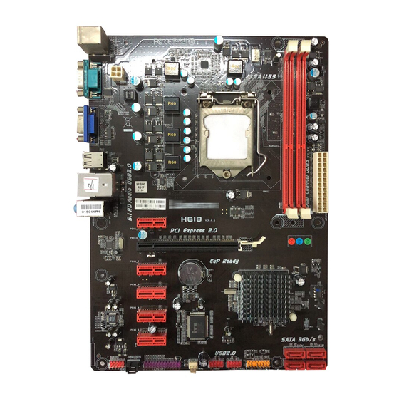
Page 7: Motherboard Layout
Motherboard Manual OTHERBOARD AYOUT KBMS1 CPU_FAN1 ATX P WR2 Socket 1155 C PU 1 USB1 RJ45USB1 AUDIO1 ATXPWR1 PEX1_1 PEX16_1 PEX1_2 PEX1_3 BIOS PEX1_4 CODEC Super JCMOS1 PEX1_5 SATA3 SATA1 J_PRINT1 SYS_FAN1 F_USB2 F_USB1 SATA4 JSPDIFOUT1 SATA2 PANEL1 F_AUDIO1 Note: represents the 1 pin. -
Page 8: Chapter 2: Hardware Installation
H6 1 B CHAPTER 2: HARDWARE INSTALLATION (CPU) NSTALLING ENTRAL ROCESSING Notice: Remove Pin Cap before installation, and make good preservation for future use. When the CPU is removed, cover the Pin Cap on the empty socket to ensure pin legs won’t be damaged. - Page 9 Motherboard Manual Step 3: Look for the triangular cut edge on socket, and the golden dot on CPU should point forwards this triangular cut edge. The CPU will fit only in the correct orientation. Step 4: Hold the CPU down firmly, and then lower the lever to locked position to complete the installation.
-
Page 10: Fan Headers
H6 1 B FAN H EADERS These fan headers support cooling-fans built in the computer. The fan cable and connector may be different according to the fan manufacturer. Connect the fan cable to the connector while matching the black wire to pin#1. -
Page 11: Installing System Memory
Motherboard Manual NSTALLING YSTEM EMORY A. Memory Modules Unlock a DIMM slot by pressing the retaining clips outward. Align a DIMM on the slot such that the notch on the DIMM matches the break on the Slot. Insert the DIMM vertically and firmly into the slot until the retaining chip snap back in place and the DIMM is properly seated. - Page 12 H6 1 B B. Memory Capacity DIMM Socket Total Memory DDR3 Module Location Size DDR3_A1 512MB/1GB/2GB/4GB/8GB Max is 16GB. DDR3_B1 512MB/1GB/2GB/4GB/8GB C. Dual Channel Memory Installation Please refer to the following requirements to activate Dual Channel function: Install memory module of the same density in pairs, shown in the table. Dual Channel Status DDR3_A1 DDR3_B1 Disabled Disabled...
-
Page 13: Connectors And Slots
Motherboard Manual ONNECTORS AND LOTS SATA1~SATA4: Serial ATA2 Connectors The motherboard has a PCI to SATA Controller with 4 channels SATA2 interface, it satisfies the SATA 2.0 spec and with transfer rate of 3.0Gb/s. Assignment Ground Ground SATA3 SATA1 SATA SATA2 Ground ATXPWR2: ATX Power Source Connector... - Page 14 H6 1 B ATXPWR1: ATX Power Source Connector This connector allows users to connect 24-pin power connector on the ATX power supply. Assignment Assignment +3.3V +3.3V -12V +3.3V Ground Ground PS_ON Ground Ground Ground Ground Ground PW_OK Standby Voltage+5V +12V +12V Ground +3.3V...
- Page 15 Motherboard Manual PEX16_1: PCI-Express Gen3 x16 Slot PCI-Express 3.0 compliant. Maximum theoretical realized bandwidth of 16GB/s simultaneously per direction, for an aggregate of 32GB/s totally. PCI-E 3.0 is supported by Core i7-3xxx / i5-3xxx CPU. PEX1_1 ~ PEX1_5: PCI-Express Gen2 x1 Slots PCI-Express 2.0 compliant.
-
Page 16: Chapter 3: Headers & Jumpers Setup
H6 1 B CHAPTER 3: HEADERS & JUMPERS SETUP OW TO ETUP UMPERS The illustration shows how to set up jumpers. When the jumper cap is placed on pins, the jumper is “close”, if not, that means the jumper is “open”. - Page 17 Motherboard Manual F_USB1/F_USB2: Headers for USB 2.0 Ports at Front Panel These headers allow users to connect additional USB cable on the PC front panel, and also can be connected with internal USB devices, like USB card reader. Assignment +5V (fused) +5V (fused) USB- USB-...
- Page 18 H6 1 B F_AUDIO1: Front Panel Audio Header This header allows users to connect the front audio output cable with the PC front panel. This header allows only HD audio front panel connector; AC’97 connector is not acceptable. HD Audio AC’97 Assignment Assignment...
- Page 19 Motherboard Manual J_PRINT1: Printer Port Connector This header allows you to connector printer on the PC. Assignment Assignment -Strobe Ground -ALF Data 6 Data 0 Ground -Error Data 7 Data 1 Ground -Init -ACK Data 2 Ground -Scltin Busy Data 3 Ground Ground Data 4...
-
Page 20: Chapter 4: Useful Help
H6 1 B CHAPTER 4: USEFUL HELP RIVER NSTALLATION After you installed your operating system, please insert the Fully Setup Driver CD into your optical drive and install the driver for better system performance. You will see the following window after you insert the CD The setup guide will auto detect your motherboard and operating system. -
Page 21: Software
Motherboard Manual OFTWARE Installing Software 1. Insert the Setup CD to the optical drive. The drivers installation program would appear if the Autorun function has been enabled. 2. Select Software Installation, and then click on the respective software title. 3. Follow the on-screen instructions to complete the installation. Launching Software After the installation process, you will see the software icon “eHOT Line”... - Page 22 If you are not using Outlook Express as your default e-mail client application, you may need to save the system information to a .txt file and send the file to our tech support with other e-mail application. Go to the following web http://www.biostar.com.tw/app/en/about/contact.php for getting our contact information.
-
Page 23: Extra Information
Motherboard Manual BIOS Update Utility BIOS Update Utility is a convenient utility which allows you to update your motherboard BIOS under Windows system. Please refer to the detailed instructions in the section 6.1 BIOS Update Utility of Chapter 6. XTRA NFORMATION CPU Overheated If the system shutdown automatically after power on system for... -
Page 24: Ami Bios Beep Code
H6 1 B AMI BIOS B Boot Block Beep Codes Number of Beeps Description No media present. (Insert diskette in floppy drive A:) “AMIBOOT.ROM” file not found in root directory of diskette in Insert next diskette if multiple diskettes are used for recovery Flash Programming successful File read error No Flash EPROM detected... -
Page 25: Troubleshooting
Motherboard Manual ROUBLESHOOTING Probable Solution There is no power in the system. Make sure power cable is Power LED does not shine; the securely plugged in. fan of the power supply does not Replace cable. work Contact technical support. Indicator light on keyboard does not shine. -
Page 26: Chapter 5: Bios Update
CHAPTER 5: BIOS UPDATE There are three ways to update the BIOS: BIOS Update Utility, BIOS Online Update Utility and BIOSTAR BIOS Flasher. Note: The programing procedure may take minutes, please do not make any operation during the programing process. - Page 27 Motherboard Manual 6. After the BIOS Update process is finished, click on OK to reboot the system. 7. While the system boots up and the full screen logo shows up, please press the <Delete> key to enter BIOS setup. After entering the BIOS setup, please go to the Save & Exit, using the Restore Defaults function to load Optimized Defaults, and select Save Changes and Reset to restart the computer.
-
Page 28: Online Update Utility
H6 1 B NLINE PDATE TILITY 1. Installing BIOS Update Utility from the CD Driver. 2. Please make sure the system is connected to the internet before using this function. 3. Open BIOS Update Utility and click the Online Update button on the main screen. 4. - Page 29 Motherboard Manual 7. After the updating process is finished, you will be asked you to reboot the system. Click OK to reboot. 8. While the system boots up and the full screen logo shows up, press <Delete> key to enter BIOS setup. After entering the BIOS setup, please go to the Save &...
-
Page 30: Biostar Bios Flasher
BIOSTAR BIOS Flasher is a BIOS flashing utility providing you an easy and simple way to update your BIOS via USB pen drive. The BIOSTAR BIOS Flasher is built in the BIOS ROM. To enter the utility, press <F12> during the Power-On Self Tests (POST) procedure while booting up. - Page 31 Motherboard Manual 6. Select the proper BIOS file, and a message asking if you are sure to flash the BIOS file. Click Yes to start updating BIOS. 7. A dialog pops out after BIOS flash is completed, asking you to restart the system.
- Page 32 H6 1 B This page is intentionally left blank.
-
Page 33: Appendix: Spec In Other Languages
Motherboard Manual APPENDIX: SPEC IN OTHER LANGUAGES ERMAN Spezifikationen Unterstützt Execute Disable Bit / Enhanced Intel Socket 1155 SpeedStep® / Intel Architecture-64 / Extended Intel Core i7 / i5 / i3 / Pentium / Celeron Memory 64 Technology / Virtualization Technology / Prozessoren Hyper Threading Chipsatz... - Page 34 Rückseiten-E Serieller Anschluss LAN-Anschluss USB2.0-Anschluss Audioanschluss Platinengröße 210 mm (B) X 305 mm (L) Biostar behält sich das Recht vor , ohne Ankündigung OS-Unterstüt Windows XP / Vista / 7 die Unterstützung für ein Betriebssystem zung hinzuzufügen oder zu entfernen.
-
Page 35: French
Motherboard Manual RENCH SPEC Prend en charge les technologies d'exécution de bit Socket 1155 de désactivation / Intel SpeedStep® optimisée/ Processeurs Intel Core i7 / i5 / i3 / Pentium / d'architecture Intel 64 / de mémoire étendue 64 / de Celeron virtualisation / Hyper Threading Chipset... - Page 36 Port USB2.0 Fiche audio Dimensions 210 mm (l) X 305 mm (H) de la carte Biostar se réserve le droit d'ajouter ou de supprimer Support SE Windows XP / Vista / 7 le support de SE avec ou sans préavis...
-
Page 37: Italian
Motherboard Manual TALIAN SPECIFICA Supporto di Execute Disable Bit / Enhanced Socket 1155 Intel SpeedStep® / Architettura Intel 64 / Processore Intel Core i7 / i5 / i3 / Tecnologia Extended Memory 64 / Tecnologia Pentium / Celeron Virtualization / Hyper Threading Chipset Intel H61 IT8728... - Page 38 Porta USB2.0 Connettore audio Dimension 210 mm (larghezza) x 305 mm i scheda (altezza) Biostar si riserva il diritto di aggiungere o Sistemi operativi Windows XP / Vista / 7 rimuovere il supporto di qualsiasi sistema supportati operativo senza preavviso.
-
Page 39: Spanish
Motherboard Manual PANISH Especificación Admite Bit de deshabilitación de ejecución / Intel Socket 1155 SpeedStep® Mejorado / Intel Architecture-64 / Procesador Intel Core i7 / i5 / i3 / Pentium / Tecnología Extended Memory 64 / Tecnología de Celeron virtualización / Hyper Threading Conjunto de Intel H61 chips... - Page 40 Tamaño de 210 mm. (A) X 305 Mm. (H) la placa Soporte de Biostar se reserva el derecho de añadir o retirar el sistema Windows XP / Vista / 7 soporte de cualquier SO con o sin aviso previo. operativo...
-
Page 41: Portuguese
Motherboard Manual ORTUGUESE ESPECIFICAÇÕES Suporta as tecnologias Execute Disable Bit / Socket 1155 Enhanced Intel SpeedStep® / Intel Arquitecture -64 Processador Intel Core i7 / i5 / i3 / Pentium / / Extended Memory 64 / Virtualization / Hyper Celeron Threading Chipset Intel H61... - Page 42 Tomada de áudio Tamanho 210 mm (L) X 305 mm (A) da placa Sistemas A Biostar reserva-se o direito de adicionar ou operativos Windows XP / Vista / 7 remover suporte para qualquer sistema operativo suportados com ou sem aviso prévio.
-
Page 43: Polish
Motherboard Manual OLISH SPEC Obsługa Execute Disable Bit / Enhanced Intel Socket 1155 SpeedStep® / Intel Architecture-64 / Extended Procesor Procesor Intel Core i7 / i5 / i3 / Pentium / Memory 64 Technology / Virtualization Technology / Celeron Hyper Threading Chipset Intel H61 Gniazda DDR3 DIMM x 2... - Page 44 Back Panel Port Szeregowy Port LAN Port USB2.0 Gniazdo audio Wymiary 210 mm (S) X 305 mm (W) płyty Obsluga Biostar zastrzega sobie prawo dodawania lub systemu Windows XP / Vista / 7 odwoływania obsługi dowolnego systemu operacyjne operacyjnego bez powiadomienia.
-
Page 45: Russian
Motherboard Manual USSIAN СПЕЦ Поддержка технологий Execute Disable Bit / Socket 1155 (центральн Enhanced Intel SpeedStep® / Intel Architecture-64 Процессор Intel Core i7 / i5 / i3 / Pentium / / Extended Memory 64 Technology / технологии ый Celeron виртуализация / Hyper Threading процессор) Набор... - Page 46 ввода-выв USB2.0-порт ода Гнездо для подключения наушников Размер 210 мм (Ш) X 305 мм (В) панели Biostar сохраняет за собой право добавлять или Поддержка Windows XP / Vista / 7 удалять средства обеспечения для OS с или без предварительного уведомления.
-
Page 47: Arabic
Motherboard Manual RABIC اﻟﻤﻮاﺻﻔﺎت ﺗﺪﻋﻢ ﺗﻘﻨﻴﺎتExecute Disable Bit / Enhanced Intel Socket 1155 SpeedStep® / Intel Architecture-64 / Extended اﻟﻤﻌﺎﻟﺠﺔ وﺣﺪة ﻣﻌﺎﻟﺠﺎتIntel Core i7 / i5 / i3 / Pentium / اﻟﻤﺮآﺰیﺔ Memory 64 Technology / Virtualization Technology / Celeron ﺼﻞ... - Page 48 ﻣﻨﺎﻓﺬ ﻋﺪد ﻣﻨﻔﺬ ﺗﺴﻠﺴﻠﻲ اﻟﺨﻠﻔﻴﺔ اﻟﻠﻮﺣﺔ ﻋﺪد ﻣﻨﻔﺬ ﺵﺒﻜﺔ اﺗﺼﺎل ﻣﺤﻠﻴﺔ ﻋﺪد ﻣﻨﺎﻓﺬ ﻋﺪد ﻣﻘﺒﺲ ﺹﻮت اﻟﻠﻮﺣﺔ ﺣﺠﻢ ارﺗﻔﺎع ﻣﻢ ﻋﺮض ﻣﻢ ﺗﺤﺘﻔﻆBiostar ﺑﺪون أو ﺎر ﺑﺈﺥﻄ ﺗﺸﻐﻴﻞ ﻥﻈﺎم ﻷي اﻟﺪﻋﻢ إزاﻟﺔ أو إﺿﺎﻓﺔ ﻓﻲ ﺑﺤﻘﻬﺎ اﻟﺘﺸﻐﻴﻞ أﻥﻈﻤﺔ دﻋﻢ...
-
Page 49: Japanese
Motherboard Manual APANESE 仕様 Execute Disable Bit / Enhanced Intel SpeedStep® / Socket 1155 Intel Architecture-64 / Extended Memory 64 Intel Core i7 / i5 / i3 / Pentium / Celeron プロ Technology / Virtualization Technology / Hyper セッサ Threadingをサポートします チップセット... - Page 50 システムファン電源装置 CMOSクリアヘッダ 各コネクタは2つのフロントパネルUSB2.0ポートをサポ USB2.0コネクタ ートします 消費者IRコネクタ S/PDIFアウトコネクタ デジタルオーディオアウト機能をサポートします プリンタポートコネクタ 各コネクタは1つのプリンタポートをサポートします 電源コネクタ(24ピン) 電源コネクタ(4ピン) PS/2キーボード / マウス VGAポート DVI-Dポート 背面パネル シリアルポート LANポート USB2.0ポート オーディオジャック ボードサイズ 210 mm (幅) X 305 mm (高さ) Biostarは事前のサポートなしにOSサポートを追加または OSサポート Windows XP / Vista / 7 削除する権利を留保します。 2012/03/06...
- Page 51 Процессоры Кулеры и другие системы Видеокарты Блоки питания Звуковые карты охлаждения Корпуса Аксессуары для систем Модули памяти для ПК и Устройства видеозахвата охлаждения ноутбуков...
Need help?
Do you have a question about the H61B and is the answer not in the manual?
Questions and answers