Table of Contents
Advertisement
Advertisement
Table of Contents

Subscribe to Our Youtube Channel
Related Manuals for Bodine PACESETTER 2701


Summary of Contents for Bodine PACESETTER 2701
- Page 1 Artisan Technology Group is your source for quality new and certified-used/pre-owned equipment SERVICE CENTER REPAIRS WE BUY USED EQUIPMENT • FAST SHIPPING AND DELIVERY Experienced engineers and technicians on staff Sell your excess, underutilized, and idle used equipment at our full-service, in-house repair center We also offer credit for buy-backs and trade-ins •...
- Page 2 Instructions for Installation and Operation High Performance Drives for 3-Phase AC Induction Motors 115V MODELS 115V MODELS Model 2701, 1/4 HP Model 2703, 1/2 HP P/N 074 01023A (BW) Artisan Technology Group - Quality Instrumentation ... Guaranteed | (888) 88-SOURCE | www.artisantg.com...
-
Page 3: Quick Reference
QUICK REFERENCE IMPORTANT Read this manual completely and carefully. Pay special attention to all warnings, cautions, and safety rules. Failure to follow the instructions could produce safety hazards which could injure personnel or damage the control, motor, or other equipment. If you have any doubts about how to connect the control or motor, refer to the detailed sections of this manual. -
Page 4: Table Of Contents
Step 7b – Operate Inverter Using Remote Devices (optional) Step 7c – Change Other Parameters (optional) Parameter List Parameter Descriptions TROUBLESHOOTING WARRANTY copyright 2000 Bodine Electric Company. All Rights Reserved. Printed in U.S.A. Artisan Technology Group - Quality Instrumentation ... Guaranteed | (888) 88-SOURCE | www.artisantg.com... -
Page 5: Introduction
Should further information be desired or should particular problems arise which are not covered sufficiently for the user’s purpose, the matter should be referred to the Bodine Electric Company. Artisan Technology Group - Quality Instrumentation ... Guaranteed | (888) 88-SOURCE | www.artisantg.com... -
Page 6: Product Specifications
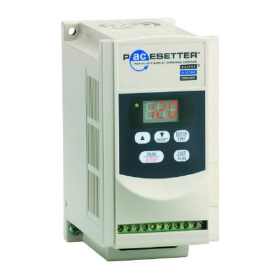
PRODUCT SPECIFICATIONS ABOUT THIS PRODUCT - Bodine’s PACESETTER “NANO” series inverter is a PWM type inverter that converts a single phase AC input voltage into an adjustable frequency three phase AC output voltage. Since the speed of AC induction motors is proportional to the line frequency, adjusting the output frequency of the inverter enables adjustable speed operation of the motor. -
Page 7: Important Safety Precautions
IMPORTANT SAFETY PRECAUTIONS The AC Drive is a power electronic device. For safety reasons, please read through this operations manual in detail and observe those paragraphs with the safety alert symbol. This is the safety alert symbol. It is used to alert you to potential personal injury hazards. -
Page 8: Installation
Check the items you received against your purchase order. The model number is printed on an adhesive label on the side of the inverter. Carefully examine the control for shipping damage. Parts errors should be reported to Bodine. Shipping damage claims should be made to the freight carrier. -
Page 9: Step 3 - Mount The Control
Step 3 – Mount the Control Install the inverter onto firm metal base or other inflammable material by inserting screws through the three 4.5 mm diameter holes in the enclosure base. DIMENSION Millimeters Inches 5.20 4.57 5.12 0.32 4.64 2.40 2.83 FIGURE 2 –... -
Page 10: Step 4 - Preliminary Setup
FIGURE 3 – Layout of several inverters inside one panel showing front view (left) and side view (right). DIN RAIL MOUNTING – Purchase Bodine’s DIN Rail Mounting Kit, model 2730, and follow the instructions that come with it. -
Page 11: Step 5 - Make Electrical Connections
Step 5 – Electrical Connections CAUTION The PCB of the inverter is vulnerable to static electrical charges. Do not contact the PCB. Choose the appropriate power source with correct voltage settings for the input voltage specification of the AC inverter. Do not use a separate device to switch ON or OFF motor during operation. -
Page 12: Step 5B - Connect Remote Control Devices (Optional)
Step 5b – Connect Remote Control Devices (optional) The drive can be completely controlled by the keypad and it is recommended that your operate the inverter this way first to verify that it is operating properly by itself before proceeding to connect external devices to it. For remote operation, the following devices can be connected to terminal block TM2. -
Page 13: Step 5C - Ground The Inverter
Step 5c – Ground the Inverter The grounding terminal of the inverter must be correctly grounded in compliance with 200V class type three grounding. Grounding wire should be wired in accordance to electrical equipment (AWG) with the length of the grounding wire as short as possible. The grounding wire of the inverter must not be grounded together with other large current loading (such as soldering machine or large power motor). -
Page 14: Step 6 - Check System Before Starting
OPERATION Step 6 – Check System Before Starting WARNING Recheck all connections. Do not remove the front cover of the inverter when the power is ON to avoid personnel injury caused by electrical shock. When the automatic restart function is enabled, the motor and machinery will be restarted automatically. -
Page 15: Step 7: Operate The Control
Step 7: Operate the Control FIGURE 9 – Keypad location and layout Step 7a – Operate the Inverter using the Keypad The PACESETTER “NANO” series inverter is factory-set for operation using the pushbutton keypad. Use the following procedure to start the motor and adjust speed. Turn the AC power ON. -
Page 16: Step 7C - Change Other Parameters (Optional)
Switch on the AC power. Press the “DSP/FUN” key. The LED display will change from set output frequency to a function number between “F00” and “F30”. Press either the “q/RESET” key or the “p” key to scroll through the available function numbers until you reach “F11”. This is the function that enables remote control of speed adjustment. - Page 17 Paramter List, Functions F12 – F27 Function Description Range Factory setting Switching frequency 001: 4 kHz 006: 10 kHz 002: 5 kHz 007: 12 kHz 003: 6 kHz 008: 14.4 kHz 004: 7.2 kHz 009: 15 kHz 005: 8 kHz 010: 16 kHz Torque boost adjustment 00.0 - 10.0%...
-
Page 18: Parameter Descriptions
Description of Programmable Functions F01: Acceleration Time Function F01 can be changed to adjust the acceleration time from the default setting of 5.0 seconds to any time between 0.1 and 999 seconds. Set Frequency Acceleration time = F01 x 60 Hz F02: Deceleration Time Function F02 can be changed to adjust the deceleration time from the default setting of 5.0 seconds to any time between 0.1 and 999 seconds. - Page 19 FIGURE 10 – Six different V/F settings. V/F Pattern for F05 = 002 V/F Pattern for F05 = 001 V/F Pattern for F05 = 003 (50 Hz High Starting Torque) (50 Hz General Application) (50 Hz Variable Torque) 120% 120% 120% 100% 100%...
- Page 20 F10: Start / Stop Control Method Use function F10 to select between the keypad (F10 = “000”) or an external signal (F10 = “001”) for run/stop instruction. The factory setting of F10 is “000”. When F10 = “001”, emergency stop on the keypad is enabled. F11: Frequency Command Selection Use function F11 to select where the frequency command comes from.
- Page 21 F16: DC Braking Injection Frequency Function F16 changes the frequency at which DC Braking begins during deceleration. The factory setting of 1.5 Hz can be changed to any number between 1 and 10 Hz, in increments of 0.1 Hz. F17: DC Braking Level Function F17 changes the DC braking level from the factory setting of 8.0% to any number between 0 and 20% in increments of 0.1%.
- Page 22 F21: Multi-function Output Terminal Use function F21 to change the function of output terminal from the factory setting of “Fault” signal (F21 = “003”) to either “Running” signal (F21 = “001”) or “Frequency Reached” signal (F21 = “002”). F22: Reverse Enable Function F22 can be used to change the reverse instruction from the factory setting of “REV command enabled”...
- Page 23 F25: Return Drive to Factory Settings Function number F25 can be used to return all programmable parameters back to their factory setting (F25 = “020”) or it can be used to configure the control for the factory settings for 50 Hz power lines (F25 = “010”). F25 is restored back to “000”...
-
Page 24: Troubleshooting
If problems persist, contact your source of purchase or a Bodine Authorized Service Center and describe the problem in detail. Do not disassemble the product unless authorized by Bodine Electric Company. - Page 25 ISOLATE THE PROBLEM – If there are no obvious indications that the drive has failed (i.e. burns marks or black smoke), then don’t assume that it is the defective component. Disconnect everything except power – With nothing but power connected to the drive, is the display illuminated? Are you able to change some of the programmable functions? If so, the drive logic is okay.
- Page 26 LED DISPLAY MESSAGES – During most operating conditions, the LED display will show the output frequency of the drive. There are four special operating conditions where a text message (b.b., E.S., SP0, and SP2) is displayed to indicate the special status.
- Page 27 FIGURE 13 (CONTINUED) – LED display messages and interpretation DISPLAY REASON PROBABLE CAUSE CORRECTIVE ACTION Over-current at Transient load fluctuation Examine loading configuration steady speed Transient power supply fluctuation Put inductor on power supply input Over-current at Deceleration setting too short Adjust to longer deceleration time deceleration Over-current while...
-
Page 28: Warranty
The Bodine Electric Company will repair or replace at its option, any of its products which has been found to be defective and is within the warranty period, provided that the product is shipped freight prepaid, with previous authorization, to Bodine’s plant in Chicago, Illinois 60618 U.S.A., or to the... - Page 29 Bodine Electric Company 2500 W. Bradley Place Chicago, Illinois 60618 U.S.A. TEL: (773) 478-3515 FAX: (773) 478-3232 www.bodine-electric.com P/N 074 01023A (BW) Artisan Technology Group - Quality Instrumentation ... Guaranteed | (888) 88-SOURCE | www.artisantg.com...
- Page 30 Artisan Technology Group is your source for quality new and certified-used/pre-owned equipment SERVICE CENTER REPAIRS WE BUY USED EQUIPMENT • FAST SHIPPING AND DELIVERY Experienced engineers and technicians on staff Sell your excess, underutilized, and idle used equipment at our full-service, in-house repair center We also offer credit for buy-backs and trade-ins •...
Need help?
Do you have a question about the PACESETTER 2701 and is the answer not in the manual?
Questions and answers