Advertisement
SOLAR
INVERTER
LCD DISPLAY
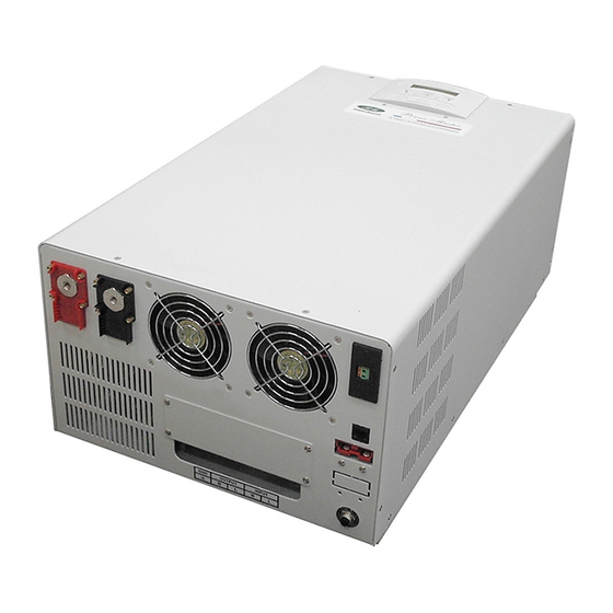
PURE SINE WAVE INVERTER
LC Series: Inverter + Battery Charger + UPS (ATS)
SLU Series: Inverter + Solar Charge Controller + Battery Charger + UPS
USER'S MANUAL
800W / 1600W / 2400W / 4000W / 6000W / 8000W
CONTENTS
1. INTRODUCTION ............................................................
2. SAFTY INSTRUCTION................................................
3. CABLE CONNECTION..................................................
4. SYSTEM DESCRIPTION..............................................
5. SOLAR INVERTER OPERATION..................................... 12
6. TROUBLE SHOOTING GUIDE......................................
8. SPECIFICATION OF SOLAR INVERTER........................ 21
1
2
3
5
6
17
19
Advertisement

Related Manuals for Power Master SLU Series


Summary of Contents for Power Master SLU Series
-
Page 1: Table Of Contents
PURE SINE WAVE INVERTER 3. CABLE CONNECTION......……..……..…..LC Series: Inverter + Battery Charger + UPS (ATS) 4. SYSTEM DESCRIPTION.....……..……..…... SLU Series: Inverter + Solar Charge Controller + Battery Charger + UPS 5. SOLAR INVERTER OPERATION........12 USER’S MANUAL 6. TROUBLE SHOOTING GUIDE.......….…..…... -
Page 2: Introduction
1. INTRODUCTION 2. SAFTY INSTRUCTION 1.1 General Description 2.1 Transporting The Solar Inverter, a powerful all-in-one solution, delivers unsurpassed clean 1. Disconnect all power cables if necessary. true sine wave output power and combines this with a selectable multistage 2. Be careful not to damage the Solar Inverter while transporting. battery charging current. -
Page 3: Cable Connection
3. CABLE CONNECTION 2.4 Operation 1. Do not disconnect the mains cable on the Solar Inverter system or the 3.1 Inspection building wiring socket outlet during operations since this would cancel the 1. The system may be installed and wired only by qualified electricians in protective earthing of the Solar Inverter system and of all connected loads. -
Page 4: System Description
4. SYSTEM DESCRIPTION 6. Warning LED (yellow): To indicate the Solar Inverter is in the status of 4.1 Front Panel Description for LCD Model overload, bypass and battery back-up. 7. Normal LED (green): To indicate the Solar Inverter is operating normally. 8. - Page 5 800W Wall Mounted Type 1600W / 2400W Rack Mount Type...
- Page 6 1600W / 2400W Wall Mounted Type 4000W / 6000W / 8000W Wall Mounted Type...
-
Page 7: Solar Inverter Operation
5. Solar Inverter OPERATION 4. LCD Display Menu Use Up/Down key to select menu-displays of the LCD described below. This 5.1 Check Prior to Start Up screen will refresh once the system power is enabled. 1. Ensure the Solar Inverter is in a suitable positioning. 2. - Page 8 Battery Status Output Voltage & Frequency Adjust A. In this screen, press Enter-key to enter the following steps for output voltage and frequency adjustment. Output Power Temperature B. The cursor (→) will pop up to indicate the output voltage and frequency newly selected.
-
Page 9: Trouble Shooting Guide
6. TROUBLE SHOOTING GUIDE 6.1 For LCD Model Charging Current Adjust The following guideline may be helpful for basic problem solving. A. In this screen, press Enter-key to No. SOLAR INVERTER STATUS POSSIBLE CAUSE ACTION enter the following steps for AC utility power is normal. -
Page 10: Operation Modes Of The Solar Inverter
7. OPERATION MODES OF THE SOLAR INVERTER No. SOLAR INVERTER STATUS POSSIBLE CAUSE ACTION 7.1 Solar Inverter System Block Diagram AC utility power fails .The 1. AC utility 1. Reduce the less load is supplied by battery power failure. critical load in power. -
Page 11: Specification Of Solar Inverter
8. SPECIFICATION OF SOLAR INVERTER 7.3 AC Utility Failure (Battery Mode) PM-0800LC PM-1600LC PM-2400LC Model The AC output comes from battery, passing through DC/AC inverter and PM-0800SLU PM-1600SLU PM-2400SLU 1.2KVA / 2.4KVA / 3.6KVA / static switch within the battery backup time. Capacity VA / Watt 800W... - Page 12 PM-4000LC PM-6000LC PM-8000LC PM-0800LC PM-1600LC PM-2400LC Model Model PM-4000SLU PM-6000SLU PM-8000SLU PM-0800SLU PM-1600SLU PM-2400SLU 5KVA / 6KVA / 8KVA / 1.2KVA / 2.4KVA / 3.6KVA / Capacity VA / Watt Capacity VA / Watt 4000W 6000W 8000W 800W 1600W 2400W Nominal Voltage 220Vac ;...
- Page 13 PM-4000LC PM-6000LC PM-8000LC Model PM-4000SLU PM-6000SLU PM-8000SLU 5KVA / 6KVA / 8KVA / Capacity VA / Watt 4000W 6000W 8000W Battery Voltage 24Vdc 48Vdc Backup Time (at full load) long time available Battery Max. Charging Current > 40A > 60A (5 steps selectable) Solar Inverter status, I/P&O/P Voltage Frequency, Load%,...
Need help?
Do you have a question about the SLU Series and is the answer not in the manual?
Questions and answers
Can I have the installation drawings for the Pm 4000SLU inverter