
Related Manuals for Kuppersbusch KE 854.1


Summary of Contents for Kuppersbusch KE 854.1
- Page 1 Service Manual VKS-H H1-50-01-02 EKE 854.1 / EKE 804.2 / EKE 604.2 Glass ceramic hob unit with sensor touch control EKE 854.1 EKE 804.2 / 604.2...
-
Page 2: Table Of Contents
Service Manual VKS-H H1-50-01-02 EKE 854.1 / EKE 804.2 / EKE 604.2 Tel.: (0209) 401-733 Date: 26.05.1998 Responsable: Rutz Fax: (0209) 401-743 Contents Your appliance at a glance / Technical data - EKE 854.1 - EKE 804.2 - EKE 604.2 Using the cooking zones Disassembling the hob Changing the Touch Control unit... -
Page 3: Your Appliance At A Glance / Technical Data Eke 854.1
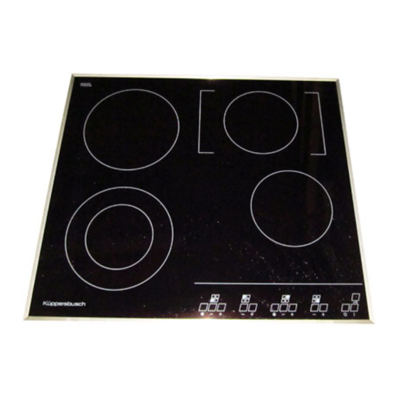
Service Manual VKS-H H1-50-01-02 EKE 854.1 Your appliance at a glance / Technical data EKE 854.1 5 cooking zones Total connected load: 8.2 kW 1 dual-circuit cooking zone 12 cm / 700 W or 18 cm / 1700 W 2 cooking zones 14.5 cm / 1200 W each (can also be used as frying zone 2400 W) 2 cooking zones 18 cm / 1800 W each Dual-circuit cooking zone Sensor keys for cooking zones... -
Page 4: Eke 804.2
Service Manual VKS-H H1-50-01-02 EKE 804.2 Your appliance at a glance / Technical data EKE 804.2 4 cooking zones Total connected load: 7.2 kW 1 dual-circuit cooking zone 12 cm / 750 W or 21 cm / 2200 W 1 cooking zone 14.5cm / 1200 W 1 dual-circuit frying zone 14 cm / 1100 W or 24.0 cm/ 2000 W 1 cooking zone 18 cm / 1800 W Dual-circuit cooking zone... -
Page 5: Eke 604.2
Service Manual VKS-H H1-50-01-02 EKE 604.2 Your appliance at a glance / Technical data EKE 604.2 4 cooking zones Total connected load: 6.7 kW 1 dual-circuit cooking zone 12 cm / 700 W or 18 cm / 1700 W 1 cooking zone 14.5cm / 1200 W 1 dual-circuit frying zone 14 cm / 1100 W or 24.0 x 14.0 cm/ 2000 W 1 cooking zone 18 cm / 1800 W Dual-circuit cooking zone... -
Page 6: Using The Cooking Zones
Service Manual VKS-H H1-50-01-02 EKE 854.1 / EKE 804.2 / EKE 604.2 Using the cooking zones Touch the sensor pad for approx. 2 seconds. The LED display above the pad will then light up and the appliance will go into operation (standby mode). The standby mode automatically switches itself off, if - no cooking zone is activated within 20 minutes (after 10 seconds an acoustic signal will indicate that the appliance... - Page 7 Service Manual VKS-H H1-50-01-02 EKE 854.1 / EKE 804.2 / EKE 604.2 Operating time in seconds The temperature of the cooking zones is time-adjusted, in the same way as the energy control unit. Depending on the cooking setting, the corresponding cooking zone will be switched on or off as described in the following table.
- Page 8 Service Manual VKS-H H1-50-01-02 EKE 854.1 / EKE 804.2 / EKE 604.2 The automatic boost function All cooking zones are equipped with an automatic boost function. Maximum power is used for the boost. The time period of the boost depends on the selected cooking setting. After the time has elapsed the cooking zone automatically switches back to the selected cooking setting.
- Page 9 Service Manual VKS-H H1-50-01-02 EKE 854.1 / EKE 804.2 / EKE 604.2 Dual-circuit cooking zones and frying zones Usually the cooking zone with the smaller diameter heats up. Switch on the outer cooking zone circuit for bigger saucepans or frying pans. Press the cooking zone symbol next to the plus/ minus pad.
- Page 10 Service Manual VKS-H H1-50-01-02 EKE 854.1 / EKE 804.2 / EKE 604.2 Childproof lock (sensor lock) Operating the sensor lock prevents unauthorised persons from using the appliance. In order to activate this lock the hob has to be in operation. Activating the lock: Press the sensor lock for 2 seconds.
-
Page 11: Disassembling The Hob
Service Manual VKS-H H1-50-01-02 EKE 854.1 / EKE 804.2 / EKE 604.2 Disassembling the electric hob Slide the lifter as far as it will go under the back or the sides of the hob (never under the front). Press the lifter onto the worktop, the hob is lifted off the clips. -
Page 12: Changing The Touch Control Unit
Service Manual VKS-H H1-50-01-02 EKE 854.1 / EKE 804.2 / EKE 604.2 Changing the Touch Control unit Electronic components and electronic modules are always sensitive to high voltage. The Touch Control unit is equipped with C-MOS-components which are very sensitive to electrostatic charging. Equipotential bonding should be performed by simultaneously taking hold of the conductive protection bag of the Touch Control unit and the metal case of the hob. - Page 13 Service Manual VKS-H H1-50-01-02 EKE 854.1 / EKE 804.2 / EKE 604.2 exchange connectors, remove the Touch Control unit, rotate it by 180° and place it on the assembly board as shown in the diagram. Insert the AMP plugs into the slots on the new Touch Control unit, making sure that they are in the right...
-
Page 14: Installing The Touch Control Unit
Service Manual VKS-H H1-50-01-02 EKE 854.1 / EKE 804.2 / EKE 604.2 Installing the Touch Control unit Before the Touch Control unit is installed, align the metal brackets. Make sure that all the springs are on the metal parts. Install washers in addition to the front springs. -
Page 15: Returning The Touch Control Unit
Service Manual VKS-H H1-50-01-02 EKE 854.1 / EKE 804.2 / EKE 604.2 Returning the Touch Control unit Electronic components must always be treated with care and specially protected during transport. Furthermore, we request you to be very careful when disassembling the components as they are recycled to save costs. -
Page 16: Aligning The Glass Ceramic Hob
Service Manual VKS-H H1-50-01-02 EKE 854.1 / EKE 804.2 / EKE 604.2 Aligning the glass ceramic hob By skilfully tightening the screws (one screw, then the screw on the opposite side and so on) you can slightly adjust the position of the marked cooking zones on the glass ceramic top in relation to... - Page 17 Service Manual VKS-H H1-50-01-02 EKE 854.1 / EKE 804.2 / EKE 604.2 At the factory the electronic hob has been equipped with a temperature-proof cable with a connecting box for the oven connection cable. The connecting box is fastened to the kitchen wall behind the built-in furniture.
-
Page 18: Demonstration Setting
Service Manual VKS-H H1-50-01-02 EKE 854.1 / EKE 804.2 / EKE 604.2 Demonstration setting When the demonstration setting is activated, the glass ceramic hob can be operated normally, but all the heating elements will remain cold. activate demonstration setting carefully turn the rotary- type switch on the side of the hob base with a screwdriver as far as it... - Page 19 Service Manual VKS-H H1-50-01-02 EKE 854.1 / EKE 804.2 / EKE 604.2 Troubleshooting and remedies Problems Cause On-the-spot measures - LED display for cooking - LED display defective - Call After-Sales Service settings and heat indicator (danger of being burned, do not or only partially light as warning about temperature is not...
-
Page 20: Terminal Connection Diagram Eke 854.1
Service Manual VKS-H H1-50-01-02 EKE 854.1 Terminal connection diagram 854.1... -
Page 21: Terminal Connection Diagram Eke 804.2
Service Manual VKS-H H1-50-01-02 EKE 804.2 Terminal connection diagram EKE 804.2... -
Page 22: Terminal Connection Diagram Eke 604.2
Service Manual VKS-H H1-50-01-02 EKE 604.2 Terminal connection diagram EKE 604.2... -
Page 23: Serial Interface
Service Manual VKS-H H1-50-01-02 EKE 854.1 / EKE 804.2 / EKE 604.2 Serial interface Slot for interface cable Insert special plug through the side openings in the hob base into the multiple connector. The other side of the special plug is connected with the PC interface via Special plug a serial cable.
Need help?
Do you have a question about the KE 854.1 and is the answer not in the manual?
Questions and answers