
Subscribe to Our Youtube Channel
Related Manuals for iSP M2000

Summary of Contents for iSP M2000
- Page 1 Stitching & Bindery Products OWNERS D i v i s i o n S a m u e l S t r a p p i n g S y s t e m s MANUAL M2000 Stitching & Bindery Products...
-
Page 2: Table Of Contents
CONTENTS Section INTRODUCTION Section MAINTENANCE, TROUBLE SHOOTING AND ADJUSTMENT Section SAFETY PRECAUTIONS AND PROCEDURES Section ASSEMBLIES, LUBRICATION, INSTALLATION Section OPERATION USE ONLY REPLACEMENT Section PARTS LIST PARTS DESIGNED AND MANUFACTURED BY ISP SPECIFICALLY FOR YOUR M2000 STITCHER... -
Page 3: Section 1 Introduction Section
Section INTRODUCTION M2000 STITCHER HEAD When ordering parts or requesting information, please state: Quantity required, part number, part name, model, wire size, crown width, stitcher head part number, and stitcher head serial number. - Page 4 PRODUCT SPECIFICATIONS Notes...
-
Page 5: Safety Precautions And Procedures
Section SAFETY PRECAUTIONS AND PROCEDURES SAFETY DANGER KEEP HANDS CLEAR OF STITCHING AREA CAUTION FOR YOUR SAFETY, MAKE SURE COVERS ARE PROPERLY IN PLACE BEFORE OPERATING MACHINE... -
Page 6: Assemblies, Lubrication, Installation
Section ASSEMBLY,LUBRICATION, INSTALLATION Note: ASSEMBLY (CTTT2605 Scene 3, Scene 4) THREADING WIRE AND ADJUSTING WIRE STRAIGHTENERS (See fig. 1) - Page 7 FELT WIPE PADS LUBRICATION AND MAINTAINANCE: (FIGURE 2) NOTE: MUST When changing coils or wire sizes, check straighteners to insure proper wire feed. CAUTION Do not operate stitcher until operating instructions have been read and understood-do not operate stitcher at anytime without work under the head.
- Page 8 (CTTT2605 Scene 5) (CTTT2605 Scene 6) STITCHING HEAD LUBRICATION: (FIGURES 3 & 4)
-
Page 9: Section 4 Operation
Section Changing Work Thickness: (Figure 5) OPERATION General: WARNING Prevent accidents by following these rules: 1. Do not put your hands near area to be stitched when machine is operating. 2. Turn the power off when the stitcher is not in use. CAUTION AVOID DAMAGE TO YOUR STITCHER BY FOLLOWING... -
Page 10: Maintenance,Trouble
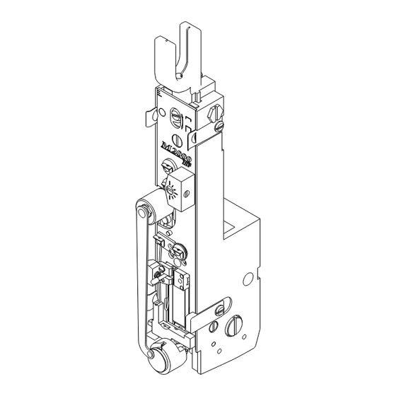
Section MAINTENANCE,TROUBLE SHOOTING AND ADJUSTMENTS General (CTTT22605 Scenes 5 & 9) (CTTT2605 Scene 8) Caution MAKE ALL ADJUSTMENTS Recommended Spare Parts WITH THE POWER OFF AND THE STITCHING HEAD IN NEUTRAL POSITION! (Fig. 6) In neutral position, the wire grip assem- bly (Index A) is stopped at the top of the slot in the face plate. - Page 11 M2000 Head Trouble Shooting HERE'S HOW A PERFECT STITCH LOOKS REMEDY TROUBLE POSSIBLE CAUSE A. Defective Stitches...
- Page 12 M2000 Head Trouble Shooting POSSIBLE CAUSE TROUBLE REMEDY...
- Page 13 M2000 Head Trouble Shooting POSSIBLE CAUSE TROUBLE REMEDY B. WIRE BUCKLES (CTTT2605 Scene 10 VA) (CTTT2605 Scene 10 VB) C. GRIP...
- Page 14 STITCH CAUTION Turn Power OFF Before making Any Adjustments A. Insufficient or Excessive Compression STITCH (SK852F) B. Clincher (Figure 8)
- Page 15 (CTTT2605 Scene 11) (SK852I) (CTTT2605 Scene 12) C. Head/Clincher Alignment (Figure 9, 10) D. Bender Bar (Figure 11)
- Page 16 (CTTT2605 Scene 13) E. Bender Bar Friction Plug And/Or Spring (Fig.12) (CTTT2605 Scene 14) F. Driver Bar (Figure 13)
- Page 17 (CTTT2605 Scene 15) H. Grip, Grip Release Slide and Face Plate: (Figure 14) G. Bender Bar Latch...
- Page 18 (CTTT2605Scene 16) I. Wire Cutters: (Figure 15) NOTE To Re- To Reverse, Interchange or place Face Plate (See Steps 1 through 10, "J" Replace the Wire Cutters: page 17). NOTE: (Figure 16) The lug (Index C) in the faceplate must match the slot (Index D) in the grip release adjusting lever (Index E) or damage to the head may result.
- Page 19 K. Proper Wire (CTTT2605 Scene 17) J. Wire Cutter Operating Slide L. Rotator (Figure 15)
- Page 20 (CTTT2605 Scenes 3 &4) M. Wire Straighteners: (Figure 17)
- Page 21 (CTTT2605 Scene 11) (CTTT2605 Scene 18) NOTE: N. Supporter O. Tension Pawl: (Figure 19)
- Page 22 DISMANTLING M2000 STITCHING HEAD CAUTION As a precautionary measure-When remov- ing the head from any stitching machine The rotator operating cam can be installed backwards. Be sure to read make SURE that the power to the ma- and follow the instructions "F"on page chine has been turned OFF or discon- 21 before reassembling.
- Page 23 DISMANTLING/REASSEMBLING M2000 HEAD 17. Loosen face plate clamp screw and slide out face plate locating block. 15. Remove screw 16. Slide tension spring bracket and adjusting lever from top. Remove rotator operating cam stud screw. 18. Slide the driving slide and bender bar assemblies from the top.
-
Page 24: Parts List
Section PARTS LIST (CTTT2605 Scene 24, CB75B Iso View) (CTTT2605 Scene 25) (SK885 Scene 2) (SK885 Scene 1) - Page 25 (SK852R) (CTT2604L Layout 2) (CA44 Layout 2)
- Page 26 1/2" Cr. CA-2007-A CA9012N 1/2" Cr. (McCain) DRIVING SLIDE SPRING a,b,c,d,f CA-9006 BONNET CASTING SUB ASSEMBLY CA-9006-A DRIVING SLIDE SPRING SCREW M2000 Heads that use bonnet sub assembly a,b,c,d,f CA-9021-A CAA2004 CAAA2005,B,R DRIVING SLIDE SPRING PIN CAA2004B CAAA2005J D-37327-F CAA2004E CAAA2005F, G (R.H.
- Page 27 1/2" Cr. (All other 1/2" Cr Heads not listed above) (for use with CA-9043-M Rotator Holder only) CA9022J GRIP RELEASE SLIDE, 1/2" Crown CAA9038E M2000 ROTATOR, 1/2" CROWN FACE PLATE ADJUSTING LEVER ROTATOR HOLDER SCREW CA9025 For Non-Slotted Face Plates...
- Page 28 (CTT9086A Layout 2, CTT9086M Layout 2, CTT9086V Layout 2) (SK852G2) (SK852H2) (CA9085A Layout 2) (SK852J2) (SK852K2) (SK852L2) (SK852I2) (SK852M2) (SK852N2) (SK85202) (SK852P2) (SK852Q2) (SK852R2) Adjustable...
- Page 29 (SK883 Scene 5) ITEM PART NO. DESCRIPTION ITEM PART NO. DESCRIPTION See Figures 20 WIRE GUIDE SPRING ASSEMBLY CB651E SCREW, 10-32 x 2.000 CAAA2133W CA9651 WASHER CAAA2133L4 CA9652 FELT WASHER, THICK CAAA2133B2 CA9653 FELT WASHER, THIN CAAA2133L5 CA9032C SPRING, COMPRESSION CAAA2133R2 CB860B NUT, 10-32, ELASTIC STOP...
Need help?
Do you have a question about the M2000 and is the answer not in the manual?
Questions and answers