Table of Contents
Advertisement
Quick Links
Operator's manual for Attachment
Operator's
Operator's
Operator's
Product number:
Please read this manual carefully before using the equipment, and follow all
instructions.
Keep this manual for later reference.
manual for Attachment
manual for Attachment
manual for Attachment
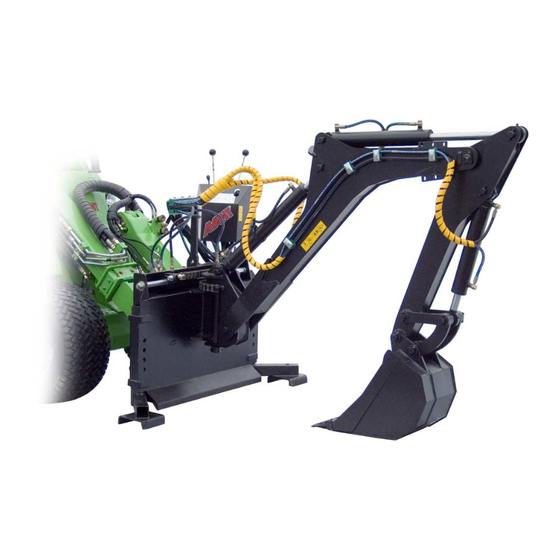
Backhoe 220 & 250
400-700-series loaders:
Backhoe 220 250 2011 1
A21172
A21155
Advertisement
Table of Contents

Related Manuals for AVANT Backhoe 250


Summary of Contents for AVANT Backhoe 250
- Page 1 Backhoe 220 250 2011 1 Operator’s Operator’s manual for Attachment manual for Attachment Operator’s Operator’s manual for Attachment manual for Attachment Backhoe 220 & 250 Product number: 400-700-series loaders: A21172 A21155 Please read this manual carefully before using the equipment, and follow all instructions.
-
Page 2: Table Of Contents
Backhoe 220 250 2011 1 CONTENTS 1. Foreword ..............................3 2. Designed purpose of use ........................3 3. Safety instructions for the backhoes......................3 4. Backhoe specifications..........................4 5. Assembly of the backhoe ........................5 5.1.Mounting kit A48130 ........................6 5.1.1.Contents of the mounting kit......................6 5.1.2.Mounting the lower adapter brackets for hydraulic locking ............6 5.1.3.Mounting the valve support bracket ...................7 5.2. -
Page 3: Foreword
3(18) 1. Foreword Avant Tecno Oy would like to thank you for your purchase of this AVANT attachment. It has been designed and manufactured on the basis of years of product development and experience. By familiarising yourself with this manual and following the instructions, you ascertain your safety and ensure the reliable operation and long service life of the equipment. -
Page 4: Backhoe Specifications
4(18) • Start the use of the backhoe carefully and calmly at a safe area • Keep others away from the operating area of the backhoe due to crushing hazard. • Turn the auxiliary hydraulics of the loader off immediately after active use of the backhoe to prevent accidental movements of the backhoe. -
Page 5: Assembly Of The Backhoe
5(18) *Normally the installation kit A48130 is supplied with the backhoe. The installation for 300-series loaders and 500-series, manufactured before 2008, depends on the boom type. Contact AVANT dealer for more information. Table 2 – Bucket options Product number: A2896... -
Page 6: Mounting Kit A48130
Mounting kit A48130 These instructions for the mounting kit A48130 are applicable to all 400-, 600-, and 700-series loaders, as well as to 500-series loaders manufactured in 2008 or later. Contact your AVANT dealer if using the backhoe with other loader models. -
Page 7: Mounting The Valve Support Bracket
7(18) 5.1.3. Mounting the valve support bracket The backhoe can be operated from two operating positions. The control valves are mounted to the loader so that it can be operated by standing next to the loader, or the valve may be mounted on the loader boom to be operated from the driver’s seat. -
Page 8: Mounting The Backhoe To The Loader
8(18) 5.2. Mounting the backhoe to the loader Mounting the backhoe to the loader must be done carefully. The backhoe may tip over on the loader or the operator, if it has not been properly attached. To prevent hazardous situations, always follow the attachment mounting instructions provided in the following pages. -
Page 9: Taking The Backhoe Off From The Loader
9(18) Step 4: Fitting the support bracket • Lift the backhoe slightly off the ground. Remove the pin from the loader side of the supporting bracket and place the bracket on the bracket of the loader boom. • Tilt the backhoe to align the holes. •... -
Page 10: Control Valve Of The Backhoe
10(18) In other cases the pressure left in the system must be relieved by opening the hose fitting slightly with tools. Keep both of the hoses disconnected and wrap the fitting in a cloth to prevent oil spillage. When the fitting is opened slightly, a small amount of oil will be released;... -
Page 11: Instructions For Use
11(18) 6. Instructions for use When the installing kit of the backhoe and the backhoe are mounted on the loader the work can be started. The control levers of the backhoe will operate once the auxiliary hydraulics of the loader has been locked on. Use the outriggers and the hydraulic locking of the backhoe;... -
Page 12: Digging With The Backhoe
12(18) The locking is operated with the extra lever on the right of the control valve, shown in figure on the next page. The lever will move the brackets mounted under the backhoe and they are intended to be turned against the bottom of the loader front frame. -
Page 13: Inspections, Maintenance And Servicing
13(18) Beware of the caving in hazard at the excavation and around it. Do not drive near the edge of the hole or allow children to play near it. Do not operate the backhoe at horizontally overly tilted terrains. Transport the backhoe as low and close to the loader as possible. -
Page 14: Cleaning The Equipment
If there are signs of leaking, to check the component, hold up a piece of cardboard in the area where a leak is suspected. Finding any of these faults means that the hydraulic hose or component in question must be replaced. Spare parts are available from your nearest AVANT retailer or service point. -
Page 15: Warranty Terms
Only add the grease amount of a couple of grease press pushes at a time. 8. Warranty terms Avant Tecno Oy grants a warranty of one year (12 months) for the attachment from the date of purchase. The warranty covers repair costs as follows: •... - Page 16 SFS-EN ISO 12100-1, SFS-EN ISO 12100-2, SFS-EN 982, SFS-EN 474-4 Kuvaus: Avant-kuormainten kanssa käytettävä kaivuulaite Beskrivning: Grävaggregat; arbetsredskap för Avant lastare Description: Backhoe bucket; attachment for Avant loaders Beschreibung: Anbaubagger; Anbaugerät für Avant Radlader Mallit / Modeller / Models / Modellen: Avant Kaivuri Grävaggregat...
Need help?
Do you have a question about the Backhoe 250 and is the answer not in the manual?
Questions and answers