Table of Contents
Advertisement
Advertisement
Table of Contents

Related Manuals for AVANT 218


Summary of Contents for AVANT 218
- Page 1 English Operator’s Manual 2013-...
-
Page 2: Table Of Contents
Table of contents 200 Series TABLE OF CONTENTS INTRODUCTION .......................3 AVANT 200 SERIES WARRANTY ..................3 EC DECLARATION OF CONFORMITY ................4 HOW TO WORK SAFELY ....................5 DECAL LOCATIONS ......................6 MAIN PARTS OF THE LOADER ..................7 TECHNICAL SPECIFICATION ..................8 LOAD DIAGRAM ........................9 CONTROLS ........................10... -
Page 3: Introduction
Introduction, warranty INTRODUCTION AVANT Tecno Oy wants to thank you for purchasing this AVANT loader. It is the result of Avant’s long experience in design and manufacturing of compact loaders. We ask you that you read and understand the contents of this manual completely before operating the loader. -
Page 4: Ec Declaration Of Conformity
EC declaration of conformity 200 Series EC DECLARATION OF CONFORMITY 1. Manufacturer: Avant Tecno Oy 2. Address: Ylötie 1 FI-33470 YLÖJÄRVI FINLAND 3. Technical Construction File Location: Same as Manufacturer 4. We hereby declare that the machines listed below conform to EC Directives: 2006/42/EC (Machinery), 2004/108//EEC (EMC) and 2000/14/EC (Noise Emission). -
Page 5: How To Work Safely
Never put any part of the body or let anyone go under Never modify the loader or add attachments not the lifted boom. approved by AVANT Tecno Oy. Do not transport persons in the bucket. The machine Do not smoke during refueling or driving. -
Page 6: Decal Locations
Decal locations 200 Series DECAL LOCATIONS If any of these decals has been removed or is unreadable it should be replaced without delay. -
Page 7: Main Parts Of The Loader
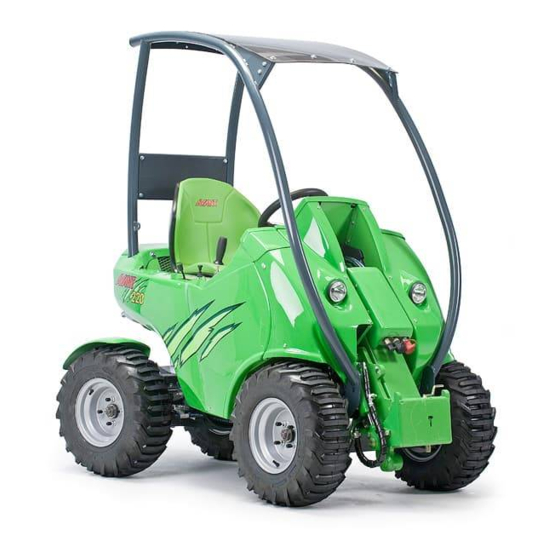
200 Series Main parts of the loader MAIN PARTS OF THE LOADER Following picture shows the main parts of the loader: Front frame Loader boom Front frame is the part of the loader in Loader boom is mounted on the front front of the articulation joint. -
Page 8: Technical Specification
92 oct. petrol min. 92 oct. Hydraulic oil tank capacity 23 l Fuel tank capacity Auxiliary hydraulics AVANT 216: 23 l/min 185 bar Engine oil capacity AVANT 220: 29 l/min 185 bar 2,0 l 2,0 l Engine oil type... -
Page 9: Load Diagram
0.75m 1.00m 0.50m 0.25m AVANT 200 series Load diagram The diagram can be interpreted as follows: • The diagrams show max. loads with the boom in different positions and with the load at different distances from the attachment coupling plate •... -
Page 10: Controls
Controls 200 Series OPERATING CONTROLS Following picture shows the location of operating controls. The location and function of controls may be slightly different in different models, see following pages. Steering wheel Choke Hour meter Drive pedal, right: drive forward Ignition switch Drive pedal, left: drive backward Signal horn Parking brake handle... - Page 11 200 Series Controls CONTROL OF LOADER BOOM, ATTACHMENTS AND OTHER FUNCTIONS Most of the functions of the loader are controlled at the control panel on the right side of the operator: Boom and bucket movements, engine revs etc.. Following pictures show the different functions: 7.
-
Page 12: Location Of Battery Disconnect Switch
LOCATION OF BATTERY DISCONNECT SWITCH All AVANT loaders are equipped with a battery disconnect switch. In AVANT 218/220 the switch is located under the drivers seat in engine compartment. Following pictures show the location of this switch. STARTING THE ENGINE (see also KOHLER Owner’s Manual) -
Page 13: Drive Control
Drive control DRIVE CONTROL AVANT 200 series loaders are equipped with a hydrostatic drive system, there is a variable displacement hydraulic pump in the drive circuit. The oil flow of this drive pump is steplessly adjusted with the two drive pedals. The drive pedals act in a proportional way to control the drive speed and power available at the drive motors. -
Page 14: Steering Of The Machine
Steering of the machine 200 Series STEERING OF THE MACHINE USING THE AUXILIARY HYDRAULICS Steering of the machine is actuated via the steering Auxiliary hydraulics (hydraulically operated attachments) wheel. The steering wheel is hydraulically powered. are controlled with the pedal no. 14 in the footwell. A practical way of steering is to steer with your left hand on the knob of the steering wheel. -
Page 15: Coupling The Attachments
200 Series Coupling the attachments COUPLING THE ATTACHMENTS Coupling of the attachments into the attachment coupling plate happens as follows: Stage 1: • Lift up the locking pin and turn it backward so that it remains in the locked up position. •... -
Page 16: Maintenance Schedule
Maintenance schedule 200 Series MAINTENANCE SCHEDULE Following table shows the maintenance and service points and intervals. There are more detailed instructions about each service operation, in numerical order, on the following pages. Every Every After After Every Every Every Every Every Every Every... -
Page 17: Safety Instructions For Maintenance
200 Series Safety instructions for maintenance SAFETY INSTRUCTIONS FOR MAINTENANCE ALWAYS REMEMBER SAFETY DURING MAINTENANCE DO NOT PERFORM ANY SERVICE OPERATION WHEN THE ENGINE IS RUNNING USE THE SERVICE SUPPORT ON THE BOOM CYLINDER DO NOT GO UNDER UNSUPPORTED BOOM DO NOT SMOKE DURING SERVICE OPERATIONS BEWARE POSSIBLE HIGH PRESSURE IN HYDRAULIC CIRCUITS SAFETY INSTRUCTIONS WHEN HANDLING THE BATTERY... -
Page 18: Maintenance Instructions
Maintenance instructions 200 Series 1. CLEANING OF THE LOADER 5. CHANGING OF HYDRAULIC OIL FILTERS Cleanliness of the loader is not only a question of The hydraulic oil return filter outer appearance. All surfaces, painted and others, is located on top of the will stay in better condition when they are cleaned hydraulic oil tank, under the regularly. - Page 19 11.-19. SERVICE, ENGINE is wrong, it can be adjusted. Following pictures show the pressure adjusting points. AVANT 218 is equipped with the Kohler CV620 petrol engine. Service and maintenance instructions Boom movements: Pressure for this engine can be found in the Kohler Operator’s is adjusted from the pressure Manual supplied with the loader.
-
Page 20: Filter Location
6. Engine oil filter 64827 Fuel filter 64824 Oil filter A3958 Breather hydr. dipstick A46683 218/220 Filter kit 64828 Spark plug GREASING POINTS Following pictures show the location of greasing points. 1. Lift cylinder, both ends 2. Self leveling bar, both ends 3. -
Page 21: Refueling
KEEP THE ENGINE AWAY FROM OPEN FIRE. DRIVE BELT AVANT 218/220 is equipped with a drive belt which connects the hydraulic pump to the engine. The belt may get loose over a long period of time and may need tightening. -
Page 22: Hydraulic System
Hydraulic system 200 Series HYDRAULIC SYSTEM A. Hydrostatic pump, with the feed pump B. Double gear pump C. Driving pedal valve D. Front wheels E. Rear wheels I J K F. F1 -Hydraulic oil return line filter F2 -Hydraulic oil high pressure filter G. -
Page 23: Troubleshooting
200 Series Troubleshooting TROUBLESHOOTING Problem Cause Remedy Hydraulic attachment does not Attachment hoses are not Make sure that the hoses are work when the auxiliary coupled or they are coupled properly connected into the hydraulics control lever is wrongly in the quick couplers. quick couplers, change the place moved. - Page 24 © 2013 AVANT Tecno Oy. All rights reserved. Printed in Finland...
Need help?
Do you have a question about the 218 and is the answer not in the manual?
Questions and answers