Table of Contents
Advertisement
Advertisement
Table of Contents

Subscribe to Our Youtube Channel
Related Manuals for FEC PP-9635

Summary of Contents for FEC PP-9635
- Page 1 Service Manual Model: PP-9635 Last Modified: 2017/1/13...
- Page 2 This document is copyrighted, © 2017. All rights are reserved. Firich Enterprises Co., Ltd. reserves the right to make changes to the product described in this manual at any time without notice. No part of this manual may be reproduced, copied, translated, or transmitted in any form or by any means without the prior written permission from Firich Enterprise Co., Ltd.
-
Page 3: Table Of Contents
Table of Contents Basic Information Technical Support Regulatory Safety Precautions Quick Start Guide Package opening Accessory Box (Standard) System Specifications 7-10 Overview Physical System Specifications I/O Interface & Options Setting Up 11-27 Installing Windows 10 Enterprise Installation Sequence for Windows 10 Enterprise Intel J1900 Chipset Utilities Audio Driver Realtek LAN Driver... -
Page 4: Basic Information
Locate the latest support items on our website: http://www.fecpos.com/en-global/ams/Download If you are a partner of FEC, you will be able to obtain an login and password to access more information: http://www.fecpos.com/en-global/member/login If you are an FEC direct partner and you do NOT have a eRMA account, send an email to our technical support staff: service@firich.com.tw... -
Page 5: Regulatory
Regulatory Standard(s) EN 55022: 2010 +AC: 2011 Class B AS/NZS CISPR 22:2009+A1:2010Class B CISPR 22:2008Class B EN55024: 2010 EN61000-3-2: 2006 +A1: 2009 +A2: 2009 Class D EN 61000-3-3: 2013 Authorized under Declaration of Conformity according to 47 CFR, Part 2 and Part 15 of the FCC Rules. The product listed in the follows was (were) tested in the BTL EMC Laboratory to comply with the criteria limits Class B of conducted and radiated emissions of the Technical Standards FCC Part 15, Subpart B, established by the FCC, USA. -
Page 6: Package Opening
1. Cut the packaging tape and bands 2. Locate the accessory box and remove it from the package 3. Place PP-9635 on a flat cushioned surface and remove the styrofoam 4. Place PP-9635 face down; cut through the tape and remove it from the bag... -
Page 7: Accessory Box (Standard)
Accessory Box (Standard) Standard items included in the accessory box includes: 1. Power Cord x 1 2. Adaptor x 1 3. Cable Cover x 1 4. RJ45 to DB9 Cable x 1... -
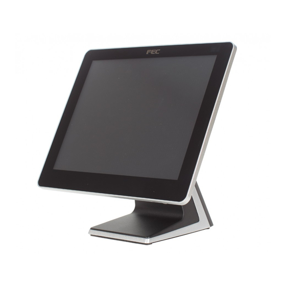
Page 8: Overview
Overview 15inch PCAP Touch Display Power Switch (LED) HDD Indicator Integrated Customer Display Add-on Device 2.5” SATA Storage MSR, iButton, Fingerprint Reader Speaker Stand... -
Page 9: Physical
Physical Dimension Display Tilt Angle 70° 90°... -
Page 10: System Specifications
System Specifications PP-9635 Platform Intel Celeron Quad Core J1900 CPU 2.0~2.4Ghz Processor Memory 1 x 2GB 204-pin DDR3L Standard ; Maximum 8GB Power Supply 90W / 150W 15” (4 : 3) Display Brightness / MTBF 300nits / 50,000 Hours (Based on 25°C Environment) - Page 11 PP-9635 Standard DC-in 1 x 12V Power USB 1 x 24V Cash Drawer 1 x RJ11 1 x GigaLAN Video 1 x DB15 1 x USB 3.0, 3 x USB 2.0 DC-out 1 x 12V Type A Standard + 2 x DB9...
- Page 12 Windows 10 Enterprise Installation 1. Select language 2. Click Install now 3. Enter the Product Key 4. Check applicable notices and license terms , Next 5. which type of installation do you want , example: install windows only 6. If you are using an old hard disk, select “Delete” remove the hard disk partition 7.
- Page 13 9. Check OK 10. Complete the hard disk partition 11. Start Install 12. The installation is complete; Check “Use Express Settings” 13. Enter User name; Click “Next”...
-
Page 14: Setting Up
Setting Up Installation Sequence 1. Chipset Driver 2. Audio Driver 3. LAN Driver 4. Graphic Driver 5. TXE Driver TXE Update 6. USB3.0 Driver 7. Touch Tools (Touch Utility) -
Page 15: Intel J1900 Chipset Utilities
Intel J1900 Chipset Utilities Note: Images are for Windows 10 Enterprise, however many divers may be the same. Refer to the FEC website under SUPPORT > DOWNLOADS to filter the correct drivers and utilities for your product.. 1. Download drivers from www.fecpos.com/en-global/ams/Download... -
Page 16: Audio Driver
Audio Driver 1. Download drivers from www.fecpos.com/en-global/ams/Download 2. run Steup.exe 3. restart PP-9635 to complete installation... -
Page 17: Realtek Lan Driver
Realtek LAN Driver 1. Download drivers from www.fecpos.com/en-global/ams/Download 2. run Steup.exe... -
Page 18: Intel Graphic Driver
Intel Graphic Driver 1. download drivers from www.fecpos.com/en-global/ams/Download 2. run Steup.exe 3. restart PP-9635 to complete installation... -
Page 19: Intel Txe Driver
Intel TXE Driver Download drivers from www.fecpos.com/en-global/ams/Download run Setup.exe restart PP-9635 to complete installation... - Page 20 Intel TXE Installation (Intel® Trusted Execution Engine) 1. Download drivers from www.fecpos.com/en-global/ams/Download 2. run kmdf1.11-win-6.1-x64.exe 3. restart PP-9635 to complete installation...
-
Page 21: Usb 3.0 Driver
USB 3.0 Driver 1. Download drivers from www.fecpos.com/en-global/ams/Download 2. run Steup.exe 3. restart PP-9635 to complete installation... -
Page 22: Elo Touchkit Tools Installation
ELO Touch Tools Installation (For PP-9635B Only) 1. Right click on ELO Touch (SW602211_ELOMouseTouch_5.5.3.exe) then click RUN as administrator 2. Click “OK” to authorize to unzip the file 3. Unzip file and start to Install USB Touch Screen Driver 4. Choose Language then click “Next” 5. - Page 23 6. Start installation and choose “Calibrate ELO ToucScreen” as finished 7. Four Corners Calibration Click on the Target as it appears 8. ELO Touchscreen Control Panel General Page You can choose either “Normal Mode” or “Enhanced Mode”...
- Page 24 9. Mode Page: Mouse Button emulation mode Click on touch, Click on release, Mouse emulation Double Click Area Options Hide arrow mouse pointer, left-hand mouse, show tool tray utility Drag delay Untouch Timeout...
- Page 25 10. Sound Page: Beep options without Beep, Beep on touch, Beep on untouch Beep from External Speaker, Motherboard Beeper Motherboard Beep settings Tone and Duration 11. Properties 1: Screen Information Align touch calibration Identify Monitor identification of 1 screen touch or 2 screen touch...
- Page 26 Advanced:...
-
Page 27: Eeti Touchkit
4. Do NOT check Install RS232 interface driver and continue 5. Confirm USB touch device is in use 6. Check Support Multi-Monitor System” and continue 7. Restart PP-9635 to complete installation Do NOT Click this box Do NOT Click this box... -
Page 28: Eeti Touchkit Control Panel
EETI TouchKit Control Panel Tools allows the user to calibrate the touch panel via 4 Points Calibration For Resistive Touch(PP-9635A) For P-Cap Touch(PP-9635C) , it doesn’t need Calibration... -
Page 29: Wireless Lan Driver For Windows
Wireless LAN Driver for Windows 1. download drivers from www.fecpos.com/en-global/ams/Download 2. run Setup.exe... -
Page 30: How To Guide
How to Guides How to Install the Stand 1. Match the two hooks from the stand to the two square holes on the panel PC. Be careful of the alignment as to not damage the paint. Slowly place the PPC down to meet the base. -
Page 31: How To Replace The Storage Device
Make sure the power is off and adaptor is unplugged before moving forward 1. Remove the side cover (Part Number: RCAIOPPC1845) 2. Install the storage device to the bracket using 4 screws (Part Number: RBAIOPMC2070) 3. Slide the storage into PP-9635 Lock in storage with 1 x M3 screw... -
Page 32: How To Install The Cable Cover
How to Install the Cable Cover 1. Connect cable to DC-in 12V Flat end facing down 2. Connect all devices Lift up the cables 3. Install the cable cover (Part Number: RCAIOPPC1515) 4. Lock in with the 2 x M3... -
Page 33: How To Open The Ppc
How to Open the PPC Read First: Make sure power is off and all of the cables and peripherals have been detached. 1. Remove the 8 screws 2. Flip the PPC so that the screen is facing up and the OSD is near your 3. - Page 34 REMOVE CABLES Read First: First follow instructions of how to open the PPC. 1. Remove the cables from the display side 2. Remove the storage device 3. Remove 7 screws 4. Lift the mother board slightly from the top end 5.
-
Page 35: How To Adjust Display Brightness
How to Adjust Display Brightness 1. Connect a USB keyboard to the system and restart/boot up 2. During boot up press “delete” key to enter the BIOS 3. Using the arrow buttons, find “Backlight brightness” under the “Chipset” tab Settings available include: 5%, 25%, 50%, 75%, 100%... -
Page 36: How To Install An Id Device (Msr / Ibutton / Rfid / Fingerprint)
How to Install an ID Device (MSR / iButton / RFID / FingerPrint) Read First: Make sure the power is off and adaptor is unplugged before moving forward Remove the side cover Install the ID device Lock in storage with 1 x M3 screw... -
Page 37: How To Install The Integrated Customer Display (Vfd & Lcm)
How to Install the Integrated Customer Display (VFD & LCM) Read First: Customer display (integrated type) is connected to COM6 Make sure the power setting is correct before the customer display is connected 5mm LCM Module (AP-2025) is 5V ... -
Page 38: How To Install The 2
How to Install the 2 Display 1. Fasten the 2 monitor to PP-9635 with 2 x M5 screw 2. Connect the VGA and 12V DC Cables... -
Page 39: How To Setup The Cash Drawer
PP-9635. You may find the jumper setting and pin definition in M/B J1900 user manual. Please refer to trouble shooting if the cash drawer cannot be detected by PP-9635 To open drawer 1 (default): port[openaddr] <= open1 wait(sleep(ms)) port[openaddr] <= close... - Page 40 Motherboard Specifications...
- Page 43 Motherboard Installation Installation Precautions The motherboard contains numerous delicate electronic circuits and components which can become damaged as a result of electrostatic discharge (ESD). Prior to installation, carefully read the user's manual and follow these procedures: • Prior to installation, do not remove or break motherboard S/N (Serial Number) sticker or warranty sticker provided by your dealer.
-
Page 44: Motherboard Specification
Motherboard Specification... -
Page 46: Motherboard Connectors
Motherboard Connectors Internal Connectors... - Page 62 BIOS...
- Page 63 Main...
- Page 64 Once you enter the BIOS Setup program, the Main Menu (as shown below) appears on the screen. Use arrow keys to move among the items and press <Enter> to accept or enter other sub-menu. Main Menu Help The on-screen description of a highlighted setup option is displayed on the bottom line of the Main Menu. Submenu Help While in a submenu, press <F1>...
- Page 65 Advanced The Advanced menu display submenu options for configuring the function of various hardware components. Select a submenu item, then press Enter to access the related submenu screen.
- Page 66 Advanced > ACPI Settings Advanced IT8786E Super IO Configuration...
- Page 69 Advanced > Hardware Monitor Advanced > S5 RTC Setting...
- Page 70 Advanced > CPU Configuration...
- Page 71 Advanced > SATA Configuration Advanced > CSM Configuration...
- Page 72 Chipset Menu...
- Page 73 Wake on LAN default is Enabled; Wake on Ring default is Disabled...
- Page 74 Chipset > USB Configuration Chipset > OS Selection Options available : Windows7 , Windows8 . Default setting is windows7, Windows 8 and later versions; Please select Windows 8.X LCD Panel Type Selecting by Internal Graphics Device by selecting appropriate setup item Options available: 1024x768(18bit) / 1024x768(24bit) / 1280x1024(24bit) / 1920x1080(24bit) / LVDS Disable...
- Page 75 Reboot with power resume Options available: Enable or Disable . Default setting is Disable; Using Linux OS reboot stuck must be selected Enable Security Menu...
- Page 76 Security > Secure Boot...
- Page 77 Security > Key Management...
- Page 79 Boot Menu...
- Page 80 Save & Exit Menu...
-
Page 81: Update Bios Version Instructions
Update BIOS Version Instructions 1. MNJ190I_F7 download 2. F7 BIOS file put on the USB bootable disc,and connect the machine 3. Turn on the power and Click “Delete button” Enter the BIOS 4. Advanced→CMS→UEFI only 5. Select USB as Boot Option #1 6. - Page 82 7. Find your USB disc, here is fs2 system configuration 8. Enter “fs2:” 9. cd F7 (Enter F7 file) 10. Type “iFPTe64.nsh MNJ190I.F7”; Press Enter 11. Start updating...
- Page 83 BIOS Settings BIOS Setting of Advanced > CSM Support > Disabled in combination with Chipset > OS Selection > Windows 8.X will not be able to enter the system Legacy OS (Windows 7 /8.X / 10) with CSM Support > Enabled and Chipset > Windows 7 will not be able to enter the system ...
-
Page 84: Troubleshooting
LVDS cable is loose or RD9000PH03DY Monitor Check if LCD Panel display on screen LCD Panel is defective PIN assignment is connected well White screen LVDS cable is loose Signal cable is loose Replace LCD module, please contact FEC service center... - Page 85 Can’t enter OS 1. Reimage RD9000PH060C Install another working HDD test again. 1. Check if LVDS cable is LVDS cable is loose or LCD connected well Monitor RA9000XC3543 Panel is defective No display Replace LCD module, please contact FEC service center...
- Page 86 (90W Adapter 2. Power on and LED no boot probably after reconnecting light on 12V 4Pin) the AC cord 3. Please contact FEC service center Power Shut 1. Replace AC outlet 2. Replace Adaptor System down during 3. Replace MB...
- Page 87 System correct as specification keeps System described beeping while 3. Replace MB power on 4. Contact FEC Service Center 1. HDD is defective 2. Cable 1. Does HDD connect well after re- Can't detect installing? RD9000PH060C 2. If not, please replace new...
- Page 88 1. Check if MCR cable is MCR cable is loose or connected well No working RD9000PH1046 2. Replace MCR module, MCR device is defective please contact FEC service center Check if LCM cable is connected AP-2025 : well RD9000PH03FK No working...
- Page 89 Part Number Check Point Check if the M/B defective or I/O RH9000MB1141 board is connected well M/B IO I/O board is FH-J190M/B BT- M/B I/O is defective defective I(E3826)1.467G Replace new M/B or check M/B:1.2 BIOS:F1 please contact FEC service center...
- Page 90 Service Parts PCAP Display Module MO-BC23 Screw (2#)M3×5 MO-PNC1 AUO P-CAP Touch Screen 15" with EETI Touch Controller MO-PNC2 Conductive EMI for Panel MO-TPC4 Touch Cable Molex51021 30cm MO-TPC3 Metal bracket for 15" Panel MO-PNC1 Gasket that comes with AUO P-CAP Touch Screen 15"...
- Page 91 MO-BC6 Aluminum die-casting back cover MO-BC16 Side MSR Cover MO-BC16 Side MSR Cover MO-BC5 Cable Cover HDD1 HDD Bracket (4 x M screw included; No Storage device Included) MO-BC14 CPU Pad...
- Page 92 Stand RBAIOPMC1531 Right Hinge RBAIOPMC1530 RMAIOPMC1935 Aluminum die cast hinge holder Left Hinge RBAIOPMC1515 Aluminum die-casting ST13 SA14E0D120nA Screws (2#)M5x10 ST14 SA14E0D100nA Screws (2#)M5x12 RCAIOPPM1165 Rubber stand SA10B0D040B0 RC9000PM2271 Rubber foot Screws (2#)M3x4...
- Page 93 (with power button) Silicon ahdhesive MO-THC2 RCAIOPPM1895 tape kit for front frame AUO P-CAPTouch Screen 15" MO-THC3 RD9000PH04BD (with EETI Touch Controller) FEC LOGO Sticker MO-THC4 RJ9000LB1426 30x8mm LCD Panel AUO 15" MO-PNC1 RD9000PH03DY 1024x768 Conductive EMI for MO-PNC2 RE9000EM14A7 Panel...
- Page 94 Top & Bottom foam MO-PNC3 RCAL97PM1070 strip for 15" LCD Left & Right foam MO-PNC4 RCAL97PM1080 strip for 15" LCD MO-TPC3 RBAIOPMC2050 Panel Bracket Touch Cable - MO-TPC4 RA9000XC3325 Molex51021 4P- PHR4P MO-BC1 RA9000XC3543 LVDS Cable MO-BC2 RA9000XC3545 PWM Cable MO-BC3 SA10B0D050B0 Screws (2#) M3×5...
- Page 95 MO-BC5 RCAIOPPC1515 Cable Cover Aluminum die- MO-BC6 RMAIOPMC2045 casting back cover MO-BC7 RA9000XC3244 VFD/LCM Cable MO-BC8 RA9000XC3568 Switch Cable MO-BC9 RA9000XC3550 Speak Cable Speaker 8ohm 2W MO-BC10 RE9000EM1043 40x20mm EMI foam strip- MO-BC11 RE9000EM14A8 125x5x2mm EMI foam strip- MO-BC12 RE9000EM14A9 67x10x8mm...
- Page 96 EMI foam strip- MO-BC13 RE9000EM14AA 14x10x8mm MO-BC14 RCTRANPM1050 CPU PAD MO-BC15 RG9000CB4282 Switch Board Plastic Monitor Side MO-BC16 RCAIOPPC1845 MSR Cover Plastic VFD cover MO-BC17 RCAIOPPC1785 with hook MO-BC18 SA10B0D050K0 Screw (2#)M3×5 MO-BC19 SA10B0D040K0 Screw (2#)M3×4 MO-BC20 SA07B0D040B0 Screw (1#) M2×4...
- Page 97 MO-BC21 SA10B0Q060K0 Screw (2#) M3×6 MO-BC22 SA10B0K060B0 Screw (2#)M3X6 MO-BC23 SA10B0D050B0 Screw (2#)M3×5 FH-J190 M/B:V1.2 RH9000MB1142 BIOS:F4 (J1900) 2GHz HDD1 ASAIOP3690 HDD Bracket 150W Adapter 12V RD9000PH01BG 4Pin COM Port RA9000XC1702 Cable(RJ45 To DB9M) Type-A Group - ASAIOP1600 DB9x2+DC2.5 Group...
- Page 98 I/O bracket for Type IOA1 RBAIOPMC2090 Power Cable - IOA2 RA9000XC3551 DCJack2.5-MiniFit2P COM Cable - IOA3 RA9000XC2933 PHDR10P-DSUB9 IOA4 RJ9000LB1699 I/O Sticker for Type A IOA5 B0050EA03A07 Pillars Type-B Group -12V ASAIOP1620 Power USBx2 Group I/O bracket for Type IOB1 RBAIOPMC2110 Power Cable - IOB2...
- Page 99 Power USB Board - IOB4 RG9000CB4290 12Vx2 IOB5 RJ9000LB1701 I/O Sticker for Type B IOB6 B0135A307304 Pillars Type-C Group - ASAIOP1610 USBx2+DC2.5 Group I/O bracket for Type IOC1 RBAIOPMC2100 Power Cable - DC IOC2 RA9000XC3551 Jack2.5-MiniFit2P IOC3 RA9000XC2549 I/O-USBx2 Cable IOC4 RG9000CB4291 USBx2 I/O Board...
- Page 100 IOC7 SA10B0Q060B0 Screws (2#) M3×6 Type-D Group - ASAIOP2480 DB9x2+RJ45 Group I/O bracket - RS- IOD1 RBAIOPMC2520 232+RJ45 Cable RS232 RJ45- IOD2 RA9000XC2779 JST2.0 2x5P IOD3 RA9000XC2933 COM Cable COM Port Cable - IOD4 RA9000XC1702 RJ45 to DB9M IOD5 RCAIOPPM1433 I/O Sticker for Type B IOD6 B0050EA03A07...
- Page 101 IOD1 RBAIOPMC2060 I/O bracket (Default) Power Cable - IOD2 RA9000XC3551 DCJack2.5-MiniFit2P IOD3 RJ9000LB1698 I/O Sticker (Default) PP-9635C & ASAIOP0585 AerMonitor Stand Group RCAIOPPM1165 Rubber stand Plastic Pillow - PL-3- RCAIOPPC1320 Aluminum die- RMAIOPMC1935 casting hinge holder RBAIOPMC1530 Left Hinge...
- Page 102 RBAIOPMC1531 Right Hinge Aluminum die- RBAIOPMC1515 casting Stand RC9000PM2271 Rubber Foot RCRICHPC1280 Cable Clip SA10B0D040B0 Screws (2#)M3×4 ST10 SA10B0D080B0 Screws (2#)M3×8 ST11 SA12B0F080B0 Screws (2#)M4×8 ST12 SA12B0D100K0 Screws (2#)M4×10 ST13 SA14E0D120nA Screws (2#)M5×12...
- Page 103 ST14 SA14E0D100nA Screws (2#)M5×10 PP-9635 Packing ASAIOP0100 Group Plastic Bag - RI9000PK0210 55cmx65cmx0.08mm RIAIOPPK1060 Outter Box RIAIOPPK1070 Left EPE RIAIOPPK1071 Right EPE RIITLEPK1040 Accessory Box...
- Page 104 RD9000PH1869 Silica Gel RC9000PM1371 Ziplock bags Protection Mylar film RC9000PM2318 for Monitor...
-
Page 105: Led Panel
Service Parts by Category LED Panel Item No. Parts No. Parts Description Photo Q'ty/Unit MO-PN SVPPLDY000B0 LED Panel Kit LCD Panel AUO 15" MO-PNC1 RD9000PH03DY 1024x768 MO-PNC2 RE9000EM14A7 Conductive EMI for Panel Top & Bottom foam strip MO-PNC3 RCAL97PM1070 for 15" LCD Left &... -
Page 106: Touch
Parts No. Parts Description Photo Q'ty/Unit 15" PCAP bezel free touch MO-TH SVPPT00AU1B0 panel kit Plastic front bezel for MO-THC1 RCAIOPPC161p PCAP Twin adhesive for front MO-THC2 RCAIOPPM1895 frame 15"AUO P-CAP touch MO-THC3 RD9000PH04BD panel FEC LOGO Sticker MO-THC4 RJ9000LB1426 30x8mm... -
Page 107: Touch & Panel
MO-TPC) Plastic front bezel MO-THC1 RCAIOPPC161p for PCAP Twin adhesive kit MO-THC3 RCAIOPPM1895 for front frame 15"AUO PCAP MO-THC4 RD9000PH04BD touch panel FEC LOGO Sticker MO-THC5 RJ9000LB1426 30x8mm 15" AUO LED MO-PNC1 RD9000PH03DY Panel 1024x768 Conductive fabric MO-PNC2 RE9000EM14A7 320x50mm... - Page 108 Poron strip MO-PNC3 RCAL97PM1070 upper&lower Poron strip left & MO-PNC4 RCAL97PM1080 right Metal bracket for MO-TPC3 RBAIOPMC2050 15" Panel Touch Cable MO-TPC4 RA9000XC3325 Molex51021 30cm...
- Page 109 Item No. Parts No. Parts Description Photo Q'ty/Unit Type-A Group - ASAIOP1600 DB9x2+DC2.5 Group I/O bracket for IOA1 RBAIOPMC2090 Type A Power Cable - IOA2 RA9000XC3551 DCJack2.5- MiniFit2P COM Cable - IOA3 RA9000XC2933 PHDR10P-DSUB9 I/O Sticker for IOA4 RJ9000LB1699 Type A IOA5 B0050EA03A07 Pillars...
- Page 110 Power Cable - IOB2 RA9000XC3552 MiniFit2P- MiniFit2P IOB3 RA9000XC2549 I/O-USBx2 Cable Power USB IOB4 RG9000CB4290 Board - 12Vx2 I/O Sticker for IOB5 RJ9000LB1701 Type B IOB6 B0135A307304 Pillars Type-C Group - ASAIOP1610 USBx2+DC2.5 Group I/O bracket for IOC1 RBAIOPMC2100 Type C Power Cable - DC IOC2 RA9000XC3551...
- Page 111 IOC6 B0135A307304 Pillars IOC7 SA10B0Q060B0 Screws (2#) M3×6 Type-D Group - ASAIOP2480 DB9x2+RJ45 Group I/O bracket - RS- IOD1 RBAIOPMC2520 232+RJ45 Cable RS232 IOD2 RA9000XC2779 RJ45-JST2.0 2x5P IOD3 RA9000XC2933 COM Cable COM Port Cable - IOD4 RA9000XC1702 RJ45 to DB9M I/O Sticker for IOD5 RCAIOPPM1433...
- Page 112 Non I/O Group ASAIOP1790 (Default) I/O bracket IOD1 RBAIOPMC2060 (Default) Power Cable - IOD2 RA9000XC3551 DCJack2.5- MiniFit2P I/O Sticker IOD3 RJ9000LB1698 (Default)
-
Page 113: Stand
Stand Item No. Parts No. Parts Description Photo Q'ty/Unit PP-9635 & AerMonitor ASAIOP0585 Stand Group RCAIOPPM1165 Rubber stand RCAIOPPC1320 Plastic Pillow - PL-3-V0 Aluminum die-casting RMAIOPMC1935 hinge holder RBAIOPMC1530 Left Hinge RBAIOPMC1531 Right Hinge Aluminum die-casting RBAIOPMC1515 Stand... - Page 114 RC9000PM2271 Rubber Foot RCRICHPC1280 Cable Clip SA10B0D040B0 Screws (2#)M3×4 ST10 SA10B0D080B0 Screws (2#)M3×8 ST11 SA12B0F080B0 Screws (2#)M4×8 ST12 SA12B0D100K0 Screws (2#)M4×10 ST13 SA14E0D120nA Screws (2#)M5×12 ST14 SA14E0D100nA Screws (2#)M5×10...
-
Page 115: Packing
Packing Item No. Parts No. Parts Description Photo Q'ty/Unit ASAIOP0100 PP-9635 Packing Group Plastic Bag - RI9000PK0210 55cmx65cmx0.08mm RIAIOPPK1060 Outter Box RIAIOPPK1070 Left EPE RIAIOPPK1071 Right EPE RIITLEPK1040 Accessory Box RD9000PH1869 Silica Gel... - Page 116 RC9000PM1371 Ziplock bags Protection Mylar film for RC9000PM2318 Monitor...
Need help?
Do you have a question about the PP-9635 and is the answer not in the manual?
Questions and answers