Table of Contents
Advertisement
1
2
3
4
4.4.1
4.4.2
4.4.3
4.4.4
4.4.5
4.4.6
4.4.7
4.4.8
80545C_MHW_GF_VEDO-ML_01-2013_ENG
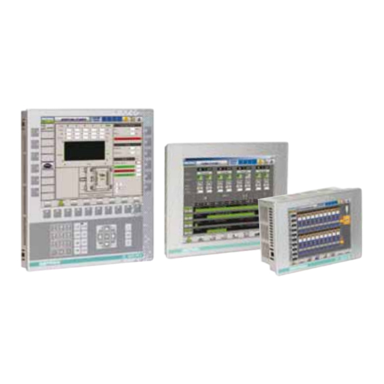
GF_VEDO serie ML
Control Panel
GENERAL INDEX
page
2
2
2
3
3
3
4
4
4
4
4
5
5
6
7
8
12
12
12
12
13
14
15
15
16
16
17
18
18
INSTALLATION AND
OPERATION MANUAL
code 80545C / Edition 04 - 01-2013
4.4.9
4.4.10 Mouse and keyboard
PS2 port
4.4.11 Memory mass Compact
Flash
5
6
The contents of each section are summarized
immediately following the section heading
page
19
19
20
20
21
21
21
22
24
24
1
Advertisement
Table of Contents

Related Manuals for gefran GF_VEDO ML Series


Summary of Contents for gefran GF_VEDO ML Series
-
Page 1: Table Of Contents
GF_VEDO serie ML Control Panel INSTALLATION AND OPERATION MANUAL code 80545C / Edition 04 - 01-2013 GENERAL INDEX page page Preface 4.4.9 Matrix Keyboard port Graphic symbols used (Key & LED) 4.4.10 Mouse and keyboard Preliminary warnings PS2 port 4.4.11 Memory mass Compact Preliminary instructions Flash General description... -
Page 2: Preface
This manual is the sole property of GEFRAN S.p.A. Gefran S.p.A. does not issue any type of guarantee with The information in this manual is reserved and regard to this manual, including but not limited to implicit confidential. -
Page 3: Preliminary Instructions
Gefran Customer Service Assistance. Users and/or system integrators who want more detailed information on serial communication between S.N: ......(N° of series) standard PCs and/or Gefran Industrial PCs and Gefran CODE: ......(Product code) Programmable Instruments may access the various TYPE: ...... -
Page 4: Installation And Connection
Remember that lack of observation of these replace the operator panel. warnings could lead to problems of electrical • Only Gefran personnel or personnel authorized by safety and electromagnetic compatibility, as Gefran may do repairs. well as invalidating the warranty. • Use only a soft damp cloth to clean the front panel and the screen. Terminal power supply SWITCH OFF THE POWER before cleaning the opera- • The GF_VEDO ML is NOT equipped with an On/Off... -
Page 5: Notes Concerning Electrical Safety And Electromagnetic Compatibility
EEC Directive 2004/108/CE. in these Instructions for Use. GF_VEDO ML series are mainly designed to operate in industrial environments, installed on the switch boards or control panels of productive process machines or plants. -
Page 6: Architecture
ARCHITECTURE /TCP ethernet RS485 RS232 CF Card 80545C_MHW_GF_VEDO-ML_01-2013_ENG... -
Page 7: Dimensions
Dimensions Horizontal models (see table) Table dimensions frame dima Model 6.5” touch 65CT 187.0 133.0 75.5 68.0 177.5 125.0 166.0 114.5 179.5 127.0 10.4” touch 104CT 266.0 192.5 68.5 61.0 256.0 182.5 166.0 114.5 258.0 184.0 12,1” touch 121CT 305.0 231.0 76.0 68.0... -
Page 8: Fixing
Fixing Angle of installation The operator terminal can be installed at an angle in the range of 30° and 120° as shown in figure 1. 90° 120° 30° 0° Fig 1 - Angle of installation Panel mounting of GF_VEDO ML GF_VEDO ML panels are designed for front panel installation. - Page 9 Figure 3 - Panel mounting GF_VEDO ML 104CT / GF_VEDO ML 104CK Figure 4 - Panel mounting GF_VEDO ML 121CT 80545C_MHW_GF_VEDO-ML_01-2013_ENG...
- Page 10 Figure 5 - Panel mounting GF_VEDO ML 150CT 80545C_MHW_GF_VEDO-ML_01-2013_ENG...
- Page 11 To ensure correct dissipation of the heat generated by GF_VEDO_ML terminals, provide a minimum distance “d” of 10 cm between the rear protective surfaces of the terminals and the surfaces around them. Fig 6 - Minimum distance from surfaces in panel (10 cm) If protection against water is necessary, it is essential to do as follows when installing the panel: • make the edges of the hole for the panel perfectly smooth and flat • tighten each fastening screw (or nut) until the corner of the frame touches the panel...
-
Page 12: Technical Specifications
4 • TECHNICAL SPECIFICATIONS Table 14 shows the main technical characteristics of each GF_VEDO ML version. In particular, it shows characteristics for displays, processors, storage devices and interfaces. 4.1 Supported Operating Systems GF_VEDO ML terminals offer the user various types of operating systems: • VxWorks: a real-time operating system by Wind River System. -
Page 13: Gf_Vedo Ml User Connections
4.4 GF_VEDO ML user connections The user connections specified on Table 4 are made at the bottom by means of Gefran standard and custom connectors. Fig 10 - GF_VEDO ML connector Name Description FIELDBUS [Optional] -CAN layer 2 RS232 Serial RS-232... -
Page 14: Power Supply Port
4.4.1 Power supply port Power supply: 24 V d.c. ±25%. The internal power supply is galvanically isolated and protected against polarity reverses and short circuits by a resettable fuse. The connector diagram is shown in Figure 11. Note: check that the power supply is able to deliver the power needed for correct operation of the device. The device must always be grounded. -
Page 15: Autostart Port
4.4.2 Autostart Port GF_VEDO ML uses the optional Autostart output to activate an external relay by means of a programmable internal timer. Activation requires that only the relay be powered, and to run the external devices you have to use the free contact of the relay (activation time approx. -
Page 16: Rs-232 Port
4.4.4 RS-232 Port (optional) RS-232 port lets the GF_VEDO ML dialog with RS-232 serial transmission protocol at a baud rate from 9.6 kBaud to 115 kBaud. The RS-232 port is not optically isolated and uses a 9-pin (male) D-sub connector. Signal assignment is shown in Table 7. -
Page 17: Optoisolated Can Port
4.4.6 FIELDBUS Port:Option CAN The optional CAN port lets GF_VEDO ML dialog via the serial standard (ISO 11898-1 of 2003) for the CAN (Controller Area Network) field bus, also known as CAN-bus. This protocol is specifically designed for excellent operation even in environments with strong electromagnetic noise, and can use a balanced potential line such as an RS-485 as means of transmission. -
Page 18: Usb Port
4.4.7 USB Port GF_VEDO ML uses USB ports to dialog via USB (Universal Serial Bus) serial communication standard. GF_VEDO ML terminals support version USB 2.0 (transmission up to 480 Mbit/s). The USB port connector is type USB-A (4 pins). Signal assignment is shown in Table 10. Voltage for VBUS is approximately +5 V with maximum current of 500 mA. -
Page 19: Matrix Keyboard Port (Key & Led)
4.4.9 Matrix Keyboard port (KEY & LED) GF_VEDO ML uses the KEY & LED port to communicate with series TF keyboards. It uses a high-speed full-duplex synchronous serial interface (SPI) with proprietary communication protocol. This allows scanning of the key matrix and control of off/on status of LEDs on the keyboard. The connector is an 8-pin RJ45 without LED, which allows keyboard communication and power. -
Page 20: Rotary
4.4.11 COMPACT FLASH memory cards The GF_VEDO ML is supplied with a COMPACT FLASH memory card in which the operating system, application, and user data are stored. The GF_VEDO card has a connector for COMPACT FLASH cards (Type II, 50 pins) with extraction button on the left. -
Page 21: Access To Internal System Resources
(With jumper inserted, the battery is connected to the system). Fig 24 - Battery connection jumper accessible from outside GF_VEDO ML terminals 4.6 Label The label on the rear of the product shows: - GEFRAN logo - CE mark - UL mark (if approved) and the following information:... -
Page 22: Summary Of Characteristics
5 • SUMMARY OF CHARACTERISTICS GF_VEDO ML 65CT 65CK 104CT 104CK 121CT 150CT Display Type TFT colors No. colours 262k Size 6.5” 10.4” 12.1” 15.0” Display area 132,5x99,4 211,2x158,4 246,0x184,5 304,1x228,1 (mm) Resolution SVGA SVGA XVGA 640x480 800x600 800x600 1024x768 Luminosity 500 cd/m 230 cd/m... - Page 23 5 • SUMMARY OF CHARACTERISTICS GF_VEDO ML 65CT 65CK 104CT 104CK 121CT 150CT Operating 0 ... +50°C (IEC 68-2-14) temperature Vibrations 5...9Hz sinusoid 3,5mm steady / 9...150Hz sinusoid with acceleration 1g Operating/Storage condition Storage 20° ... +70°C (IEC 68-2-14) temperature Operating/storage 5 ... 95% HR non-condensing (IEC 68-2-3) humidity Faceplate 187x133x75,5 187x230x76 266x192,5x68,5 266x289x76...
-
Page 24: Technical-Commercial Information
As stated in the Preliminary Warnings of these Instructions for Use, correct interpretation of the Controller order code allows the hardware configuration for the controller to be identified immediately and so it is essential to quote the order code each time the Gefran Customer Care Service is contacted for assistance with any problems. Order code...
Need help?
Do you have a question about the GF_VEDO ML Series and is the answer not in the manual?
Questions and answers