Advertisement
Quick Links
LED
State
Description
Link (left) and
Not connected to the network.
Activity (right) Off
Ports 1 and 2
Link (left) Green
Connected to the network.
Activity (right)
Network data is being sent or received.
Flashing Amber
Green
The correct cable is connected to the interface and the con-
Ports 3 and 4
nected equipment has power.
Left LED
Flashing
Network activity at this interface.
Green
The interface is connected at 1000 Mbps.
Ports 3 and 4
Amber
The interface is connected at 100 Mbps.
Right LED
Off
The interface is connected at 10 Mbps.
Blue
Normal system operation. Flashes when the System ID button is
pressed.
Blue flashing
Both the systems management software and the
identification buttons located on the front and back of the
LCD panel
system can cause the LCD to flash blue to identify a
particular system.
Amber
System requires attention due to a problem with power supplies,
fans, system temperature, or hard drives.
On
Indicates that power is supplied to the system and the system is
operational.
Power button
Off
Indicates that no power is supplied to the system.
Power supply
Green
Power supply is operational
status indica-
tor
Power supply
Amber
Problem with the power supply.
fault
AC line status
Green
AC source is connected to power supply.
Green
Drive online.
Slow green blink-
Drive rebuilding.
ing
Blinks amber 4
Drive failed.
times per second
Hard drives
Blinks green,
Rebuild aborted.
amber, and off
Blinks green 2
Identify drive/preparing for removal.
times per second
Off
Drive ready for insertion or removal.
Package Contents
Connector
Type
Speed
Ports 1 to 4
RJ-45
10/100/1000 Base-T
CONSOLE
DB9
9600 8/N/1
USB
USB
Hard drives
1 TB
Serial
System ID
button
Video
Power
button
USB ports
connector
NMI button
Sytem ID
CD Rom
button
Ports 3 and 4
For future
use
Console
connection Video
connector
Connecting
Connect the following to the unit. Ensure the unit is placed on a stable surface or install in a standard 19 inch rack. See the FortiWeb-1000B Rack Install Guide for details.
•
Assemble the rails and install the system in the rack following the safety instructions and the rack installation instructions provided with your system.
•
Connect the system's power cable to the system.
•
Bend the system power cable into a loop and secure the cable to the bracket using the provided tie wraps.
•
Plug the other end of the power cable into a grounded electrical outlet or a separate power source such as an uninterruptible power supply (UPS) or a power distribution unit (PDU).
•
Insert an Ethernet cable into the one of the 4 ports on the FortiWeb unit. Insert the other end to the router connected to the Internet, or to the modem.
•
Press the power button on the system.
Protocol
Description
Ethernet
Copper gigabit connection to 10/100/1000 copper networks.
RS-232 serial
Optional connection to the management computer. Provides access to the command line interface (CLI).
USB
Four (2 front and 2 back) optional connections to a USB key for firmware installation.
One 3.5" 1TB hard drive is provided. Can support up to two hard drives.
Connects a serial device to the system. Baud Rate 9600, Data bits 8, Parity None, Stop bits 1.
The ID buttons on the front and back panels are used to locate a system in a rack. When one of these buttons is pushed, the LCD panel on
the front and the System Status indicator on the back flash blue until one of the buttons is pushed again.
Two (one front and one back) ports that connects to a monitor system.
Front
Drive status
Hard drives
Video
indicator
Drive activity
indicator
System ID
System status
button
indicator
Ports 1
Power supply
USB
System status
and 2
indicator connec-
tor
Back
QuickStart Guide
© Copyright 2008–2017 Fortinet Incorporated. All rights reserved.
Products mentioned in this document are trademarks or registered trademarks
of their respective holders.
Regulatory Compliance
FCC Class A Part 15 CSA/CUS
Bureau of Standards Metrology and Inspection (BSMI) – Taiwan
The presence conditions of the restricted substance (BSMI RoHS table) are
available at the link below:
https://www.fortinet.com/bsmi
December 15, 2017
Power supply
status indicator
Power supply
fault indicator
AC line status
indicator
Ethernet cables connect to
the internal network and to
the Internet (public switch
or router)
Null modem
Ethernet cables connect to
cable connects to serial
the internal network and to
port on management
the Internet (public switch
computer
or router)
1000B
16-30003-883377-20081022
Rackmount rail kit
QuickStart Guide
1000B
Tools and Documenation
Copyright 2008 Fortinet Incorporated. All rights reserved.
Trademarks
Products mentioned in this document are trademarks.
Power Cable
Straight-through
Ethernet cable
Power cable
connects to
power supply
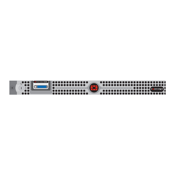
FortiWeb-1000B
R
FortiGate-30B
R
REGISTER
Null-Modem Cable
(RS-232)
Advertisement

Summary of Contents for Fortinet FortiWeb-1000B
- Page 1 (RS-232) Connecting Connect the following to the unit. Ensure the unit is placed on a stable surface or install in a standard 19 inch rack. See the FortiWeb-1000B Rack Install Guide for details. • Assemble the rails and install the system in the rack following the safety instructions and the rack installation instructions provided with your system.
- Page 2 Use the following procedure to connect to the web-based manager for the first time. Configu- The FortiWeb-1000B has serial port. Use the null modem cable to connect it to your man- ration changes made with the web-based manager are effective immediately without reset- agement computer.


Need help?
Do you have a question about the FortiWeb-1000B and is the answer not in the manual?
Questions and answers