Table of Contents
Advertisement
Quick Links
Fisher Engineering
50 Gordon Drive, Rockland, Maine 04841-2139 • www.fi sherplows.com
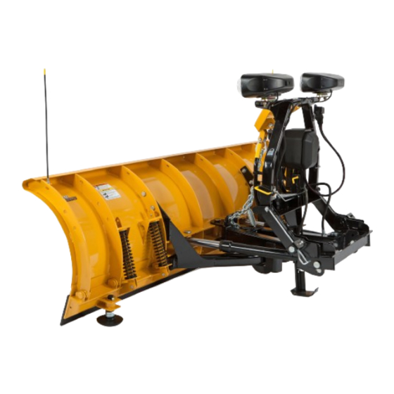
MC Series Snowplows
Installation Instructions
Read this document before installing the
snowplow.
See your FISHER
vehicle application recommendations before
installation. The eMatch selection system has
specifi c vehicle and snowplow requirements.
A DIVISION OF FISHER, LLC
CAUTION
CAUTION
outlet/website for specifi c
®
29250, 29350, 97000,
97000-1, 97100, 97100-1
April 1, 2018
Lit. No. 49599, Rev. 05
Advertisement
Table of Contents

Related Manuals for Fisher MC Series


Summary of Contents for Fisher MC Series
- Page 1 Installation Instructions CAUTION Read this document before installing the snowplow. CAUTION See your FISHER outlet/website for specifi c ® vehicle application recommendations before installation. The eMatch selection system has specifi c vehicle and snowplow requirements. A DIVISION OF FISHER, LLC...
-
Page 2: Safety Definitions
29250, 29350, 97000, 97000-1, 97100, 97100-1 SAFETY DEFINITIONS WARNING/CAUTION & INSTRUCTION LABELS WARNING Become familiar with and inform users about the Indicates a potentially hazardous situation warning labels on the back of the blade and the that, if not avoided, could result in death or instruction label on the headgear. -
Page 3: Safety Precautions
WARNING FUSES The driver shall keep bystanders clear of the The FISHER ® electrical and hydraulic systems contain blade when it is being raised, lowered, or several blade-style automotive fuses. If a problem angled. Do not stand between the vehicle and should occur and fuse replacement is necessary, the blade or within 8 feet of a moving blade. -
Page 4: Cell Phones
29250, 29350, 97000, 97000-1, 97100, 97100-1 FIRE AND EXPLOSION NOISE Airborne noise emission during use is below 70 dB(A) WARNING for the snowplow operator. Gasoline is highly fl ammable and gasoline vapor is explosive. Never smoke while VIBRATION working on vehicle. Keep all open fl ames away from gasoline tank and lines. - Page 5 29250, 29350, 97000, 97000-1, 97100, 97100-1 HEADGEAR TO A-FRAME ASSEMBLY A-FRAME TO BLADE ASSEMBLY NOTE: For easier assembly and installation, 1. Place the slots in the angle frame mounting hooks vehicle and all snowplow components should over the pins that attach the rib to the base angle. be on a smooth, level, hard surface, such as concrete.
- Page 6 29250, 29350, 97000, 97000-1, 97100, 97100-1 4. Attach the A-frame to the blade and angle frame Align the angle ram rods with the angle ram holes according to the diagram below. The A-frame on the blade. Attach with two clevis pins, installed cross member should be parallel to the blade.
-
Page 7: Hydraulic Unit
Activate the control FLOAT function and manually collapse the The MC Series snowplow hydraulic system comes lift ram all the way. Turn the control OFF. from the factory pre-assembled, partially fi lled, and fully tested. -
Page 8: Final Adjustments
29250, 29350, 97000, 97000-1, 97100, 97100-1 HEADLAMPS FINAL ADJUSTMENTS WARNING WARNING Your vehicle must be equipped with snowplow Keep 8' clear of the blade when it is being headlamps and directional lights. raised, lowered, or angled. Do not stand between vehicle and blade or directly in front of the blade. - Page 9 29250, 29350, 97000, 97000-1, 97100, 97100-1 3. Reattach the loose end of the lift chain to the If you encounter mounting or dismounting diffi culty, passenger's side of the A-frame with the retained the attachment point of the connecting link and spring U-bolt and locknuts.
- Page 10 29250, 29350, 97000, 97000-1, 97100, 97100-1 VEHICLE LIGHTING CHECK systems and the different Isolation Module options available, checking the functionality of the snowplow DRLs will depend on the type of module 1. Verify the operation of all vehicle front lighting installed on the vehicle.
- Page 11 29250, 29350, 97000, 97000-1, 97100, 97100-1 OWNER'S MANUAL PACKET If the completed snowplow will be delivered immediately, the Owner's Manual should be reviewed with and given to the purchaser according to the snowplow checklist. If the snowplow is completed prior to delivery to the purchaser, attach the Owner's Manual Packet to the electrical cable of the cab control for safekeeping.
- Page 12 Fisher Engineering reserves the right under its product improvement policy to change construction or design details and furnish equipment when so altered without reference to illustrations or specifi cations used. Fisher Engineering or the vehicle manufacturer may require or recommend optional equipment for snow removal. Do not exceed vehicle ratings with a snowplow. Fisher Engineering offers a limited warranty for all snowplows and accessories.
Need help?
Do you have a question about the MC Series and is the answer not in the manual?
Questions and answers