Table of Contents
Advertisement
Quick Links
MCP-Z Process
Betriebsanleitung
Zahnrad-Pumpen-
Antrieb
Mikroprozessor-gesteuert
ISM918A
Schutzgrad IP 65
DEUTSCH
Operating Manual Mode d'emploi
Gear pump drive
Microprocessor
controlled
ISM918A
Protection rating IP 65
ENGLISH
Moteur de pompe
à engrenages
Contrôlé par
microprocesseur
ISM918A
Classe de protection IP 65
FRANÇAIS
Advertisement
Table of Contents

Related Manuals for Ismatec ISM918A


Summary of Contents for Ismatec ISM918A
- Page 1 Operating Manual Mode d‘emploi Zahnrad-Pumpen- Gear pump drive Moteur de pompe Antrieb à engrenages Microprocessor controlled Mikroprozessor-gesteuert Contrôlé par microprocesseur ISM918A ISM918A Protection rating IP 65 Schutzgrad IP 65 ISM918A Classe de protection IP 65 MCP-Z Process DEUTSCH ENGLISH FRANÇAIS...
-
Page 2: Table Of Contents
Inhaltsverzeichnis Contents Sommaire Sicherheitsvorkehrungen Safety precautions Mesures de sécurité Garantiebestimmungen Warranty terms Conditions de garantie Produkt Product Produit Geräterückwand Rear panel Tableau arrière Netzspannung Mains voltage Tension d’alimentation Inbetriebnahme Starting the pump Mise en service Start-Information Start-up information Informations de mise en service Bedienungspanel Operating panel Tableau de commande... - Page 3 Inhaltsverzeichnis Contents Sommaire Intervall-Dosieren Intermittent dispensing Dosage par intervalles nach Zeit by time de temps nach Volumen by volume de volume Anzahl Dosierzyklen Number of dispensing cycles Nombre de cycles de dosage Mit einem Ventil dosieren Dispensing with a valve Dosage avec une soupape Pumpen gegen Druck Pumping against pressure...
-
Page 4: Sicherheitsvorkehrungen
Sicherheitsvorkehrungen Safety precautions Mesures de sécurité Die ISMATEC Zahnradpumpen ISMATEC gear pumps are de- Les pompes à engrenages ISMATEC ® ® ® sind für Förderzwecke in Labor und signed for pumping applications in sont prévues pour l’usage en laboratoire Industrie vorgesehen. Wir setzen laboratories and industry. - Page 5 Fachkraft ausgeführt werden. out by the customer or by third- Les réparations ne doivent être Durch Kunden bzw. Drittper-sonen party companies ISMATEC ® effectuées que par une personne ausgeführte Arbeiten am und im denies any responsibility. connaissant parfaitement les Gerät erfolgen auf eigene Gefahr.
-
Page 6: Garantiebestimmungen
-Vertretung. ® kostenlos in Stand gesetzt oder ersetzt. ou remplacées gratuitement. A defective pump must be returned Die Rücksendung hat in der in the original ISMATEC ® packing Le renvoi doit être effectué dans Warranty Original- oder einer gleichwertigen or in a packet of equal quality. -
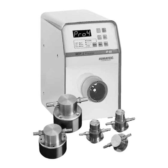
Page 7: Produkt
1 Magnet 1 magnet 1 aimant Bestell-Nr. ISM918A Order No. ISM918A No de commande ISM918A inkl. fest montiertem Netz- incl. integrated power cord, 2 m y compris câble réseau fixe kabel Länge 2 m, mit Geräte- long, with IEC 320 plug (male) longueur 2 m, avec connexion kupplung IEC 320 (männlich) -
Page 8: Geräterückwand
Geräterückwand Rear panel Tableau arrière 1. Netzschalter (ein/aus) 1. Mains switch (ON/OFF) 1. Commutateur principal 2. Netzkabel 2. Power cord 2. Prise d’alimentation 3. RS232 IN (Eingang, weiblich) 3. RS232 IN (female) 3. RS232 IN (entrée femelle) 4. RS232 OUT (Ausgang,männlich 4. -
Page 9: Inbetriebnahme
Inbetriebnahme Starting the pump Mise en service Pumpenkopf gemäß Seiten Mount the pump-head as Installer la tête de pompe selon 45 – 46 montieren. stated on Pages 45 – 46. les indications fournies en Pages 45 – 46 ou selon le mode d'emploi Die Gewinde, der in den Pum- Before screwing the tubing fourni avec la tête de pompe. -
Page 10: Start-Information
Start-Information Start-up information Informations de mise en service Die folgenden Einstellungenleuchten After switching on the power supply Les réglages suivants s’illuminent nach dem Einschalten des switch, the following values are displayed: brièvement après la mise en service Netzschalters kurz auf: de l’interrupteur de réseau: 1. -
Page 11: Bedienungspanel
Bedienungspanel Operating panel Tableau de commande 1. Digitale LED-Anzeige 1. Digital LED display 1. Affichage LED 2. Wert reduzieren 2. Reduce value 2. Réduire la valeur * settings * settings * settings 3. Wert erhöhen 3. Increase value 3. Augmenter la valeur 4. - Page 12 Bedienungspanel Operating panel Touches de commandes 8. MODE 8. MODE 8. MODE Wechselt zwischen den Betriebsarten Changes between the Changement d'un mode operating modes d'opération à un autre 9. Anzeige der aktiven Betriebsart 9. LEDs for active operating mode 9. Affichage LED du mode PROGRAM d’opération actif Programmwahl 1 –...
-
Page 13: Steuertasten Grundein-Stellungen
Steuertasten für Touches de commande pour Control keys for basic settings Grundeinstellungen réglage de base a. settings a. settings a. settings Einstieg in das Menu (réglages) accès au menu Allows access to the menu settings b. ok b. ok b. ok Eingabebestätigung Confirmation d’une saisie Confirms a data entry... -
Page 14: Cycles (Dispensing Cycles)
Programmspezifische Grund- Program specific Réglages de base spécifiques einstellungen basic settings au programme ” ” ” Für jedes der 4 Programme Individually adjustable for Réglage individuel possible individuell einstellbar. each of the 4 programs. pour chacun des 4 programmes. Cycles Cycles Cycles Anzahl Dosierungen nach Zeit bzw. -
Page 15: Valve (Ventil
Programmspezifische Program specific Réglages de base Grund-einstellungen basic settings spécifiques au programme ” ” ” Für jedes der 4 Programme Individually adjustable for Réglage individuel possible individuell einstellbar. each of the 4 programs. pour chacun des 4 programmes. Valve (Ventil, Seite 30) Valve (Page 30) Soupape (Page 30) Inactive (Default-Wert) -
Page 16: Adresse
Allgemeine General Réglages généraux Grundeinstellungen basic settings de base ” ” ” Gelten für alle 4 Valid for all 4 programs. Valables pour chacun Programme gemeinsam. des 4 programmes. Initializing 4 Initialisierung 4 Initialisation 4 Pressing the ok key resets all Durch Drücken der Taste ok werden basic settings in all 4 programs En pressant la touche ok, tous les réglages... -
Page 17: Grundeinstellungen Wählen
Grundeinstellungen wählen Selecting the basic settings Choisir les réglages de base 1. Programm wählen (Seite 18) 1. Select the program (Page 18) 1. Choisi le programme (Page 18) 2. Pumpe ausschalten 2. Switch the pump OFF 2. Couper le contact 3. -
Page 18: Programmwahl
Programmwahl Selecting the program Sélection du programme Beim Einschalten wählt die Pumpe When switching the pump ON, it always Lors de l’enclenchement de la pompe, immer das zuletzt benutzte Programm. selects the previously used program. cette dernière choisit toujours le dernier programme utilisé. -
Page 19: Pompage Selon Le Nombre De Tours
Pumpen nach Drehzahl Pumping by speed Pompage selon le nombre de tours ○ PROGRAM ● rpm ○ Flow Rate PUMP ○ Time ○ Volume DISP PAUSE ○ Time ○ TOTAL 1. Mit der MODE-Taste auf PUMP 1. Change mode to PUMP 1. -
Page 20: Nach Fließrate
Pumpen nach Fließrate Pumping by flow rate Pompage selon le débit ○ PROGRAM ○ rpm ● Flow Rate PUMP DISP ○ Time ○ Volume ○ Time ○ TOTAL PAUSE 1. Mit der MODE-Taste auf 1. Change the mode to PUMP Flow rate 1. -
Page 21: Fließrate Kalibrieren
Fließrate kalibrieren Calibrating the flow rate Calibration du débit ○ PROGRAM ○ rpm ● Flow Rate PUMP ○ Time ○ Volume DISP PAUSE ○ Time ○ TOTAL 1. Mit der MODE-Taste auf 1. Change the mode to PUMP Flow rate. 1. -
Page 22: Dosage Selon Le Temps
Dispensing by time Dosage selon le temps Dosieren nach Zeit ○ PROGRAM ○ rpm ○ Flow Rate PUMP DISP ● Time ○ Volume ○ Time ○ TOTAL PAUSE The dispensing time can be La durée de dosage peut être Die Dosierzeit kann von 0.10 s – entered from 0.10 s –... -
Page 23: Nach Volumen
Dosieren nach Volumen Dispensing by volume Dosage selon le volume ○ PROGRAM PUMP ○ rpm ○ Flow Rate ○ Time ● Volume DISP PAUSE ○ Time ○ TOTAL 1. Mit der MODE-Taste auf DISP Volume. 1. Change the mode to DISP Volume. 1. -
Page 24: Volumen Kalibrieren
Volumen kalibrieren Calibrating the volume Calibration du volume ○ PROGRAM ○ rpm ○ Flow Rate PUMP DISP ○ Time ● Volume ○ Time ○ TOTAL PAUSE 1. Mit MODE-Taste auf DISP Volume. 1. Change the MODE to DISP Volume. 1. Passer avec la touche MODE sur DISP Volume. -
Page 25: Volumen
Default-Kalibration Fließrate Default calibration of flow rate Calibration par défaut (débit) ○ PROGRAM PUMP ○ rpm ● Flow Rate ○ Time ○ Volume DISP ○ Time ○ TOTAL PAUSE 1. Mit der MODE-Taste auf 1. Change the mode to PUMP Flow rate. 1. -
Page 26: Dosage Du Volume
Volumendosierung Dispensing by volume Dosage d'un volume dans un in einer Zeiteinheit within a pre-set time intervalle de temps donné ○ PROGRAM ○ rpm ○ Flow Rate PUMP DISP ● Time ○ Volume ○ Time ○ TOTAL PAUSE 1. Mit der MODE-Taste auf DISP Time 1. -
Page 27: Intervall-Dosieren
Intermittent Dosage par intervalles Intervall-Dosieren (Zeiteinheit) dispensing (by time) (unité de temps) ○ PROGRAM PUMP ○ rpm ○ Flow Rate ○ Time ○ Volume DISP ● Time ○ TOTAL PAUSE Repetitives Dosieren nach Zeit Intermittent dispensing by time Dosage répétitif selon le temps mit vorgegebener Pausenzeit. -
Page 28: Nach Volumen
Intervall-Dosieren (Volumen) Intermittent dispensing (by volume) Dosage par intervalles (selon volume) ○ PROGRAM PUMP ● rpm ○ Flow Rate ○ Time ○ Volume DISP ● Time ○ TOTAL PAUSE Repetitives Dosieren nach Volu- Intermittent dispensing by volume Dosage répétitif selon le volume men mit vorgegebener Pausenzeit. -
Page 29: Anzahl Dosierzyklen
Anzahl Dosierzyklen Number of dispensing cycles Nombre de cycles de dosage ○ PROGRAM ○ rpm ○ Flow Rate PUMP DISP ● Time ○ Volume ● Time ○ TOTAL PAUSE Beim Dosieren in Intervallen (nach The number of dispensing cycles Lors du dosage par intervalles Zeit bzw. -
Page 30: Mit Einem Ventil Dosieren
Mit einem Ventil dosieren Dispensing with a valve Dosage avec une soupape Die Verwendung eines Ventils verhindert Using a valve prevents a syphoning Lorsqu’il s’agit d’éviter un retour du beim Anhalten der Pumpe einen effect (liquid flows back to the liquide à... -
Page 31: Pumpen Gegen Druck
Pumpen gegen Druck Pumping against pressure Pompage contre pression Der max. Differenzdruck hängt vom The max. differential pressure La pression différentielle maximale Modell des verwendeten Zahnrad- depends on the mounted pump- dépend du modèle de tête de Pumpenkopfes ab (siehe Seiten 48/49). head model (see Pages 48/49). -
Page 32: Überlastschutz
Überlastschutz Overcurrent protector Protection de surcharge Der Antrieb MCP-Z Process verfügt The drive MCP-Z Process features La pompe MCP-Z Process possède une über eine Überlast-Sicherung. Eine an overload protector. When an protection de surcharge. Un état illégal Überlastung wird im Display durch overload condition occurs, it is est indiqué... -
Page 33: Analogschnittstelle
Analogschnittstelle Analog interface Interface analogique speed IN input 1 start +36 V Pin 1, GND (Masse) Pin 1, GND (ground) Pin 1, GND (masse) remote input 2 Bezugspotential für alle Reference potential for all other inputs. Potentiel de référence pour anderen Eingänge. - Page 34 Analogschnittstelle Analog interface Interface analogique speed IN input 1 start +36 V Pin 9, speed OUT Pin 9, speed OUT Pin 9, speed OUT remote input 2 Die werkseitige Einstellung The default setting is 0 –10 V Le réglage d’usine par défaut est 0 ist 0 –10 V , proportional zur proportionally to the motor...
- Page 35 Schalter S1 Switch S1 Switch S1 4/SAT Pins Impedanz DIP-Switch 1 DIP-Switch 2 DIP-Switch 3 DIP-Switch 4 DIP-Switch 5 Dip-Switch 6 0-5V 470 kΩ OFF* OFF* OFF* 1.6 AF 0-10V 20 kΩ Pin 5 speed IN 0-20mA 240 Ω Eingang Input/Entrée 4-20mA 240 Ω...
-
Page 36: Serielle Schnittstelle
3 second delay. OFF). The assignment of the address commande de plusieurs moteurs Die Adressierung ermöglicht die enables the user to control up to 8 Ansteuerung von bis zu 8 ISMATEC ISMATEC drives via one interface. ISMATEC par le biais d’une seule ®... - Page 37 Serielle Schnittstelle Serial interface Interface sérielle RS232 OUT (Ausgang: männl.) RS232 OUT (male) RS232 OUT (sortie: mâle) Pin 2: RS232 Rx Pin 2: RS232 Rx Pin 2: RS232 Rx Dient zusammen mit Pin 3/5 zum Is used for connecting additional Employé...
-
Page 38: Befehle
Serielle Schnittstelle / Serial interface / Interface sérielle Pumpensoftware Version Zeichenerklärungen / Key to the symbols / Explications des signes 1.11 Eingabe richtig/Correct input/Saisie correcte Pump software version Eingabe falsch/Incorrect input/Saisie erronée Version du logiciel de la pompe _ _ _ _ Ziffern zwischen 0–9/Numerals between 0–9/Chiffres entre 0–9 ASCII 10 Zeilenschaltung/Line feed/Nouvelle ligne ASCII 13 (carriage return) Befehl abschließen... - Page 39 Serielle Schnittstelle / Serial interface / Interface sérielle Befehl Funktion / Beschreibung Beispiel Antwort Command Function / Description Example Response Commande Fonction / Description Exemple Réponse Zahlen für Bedienfeld schreiben (nur bei inaktivem Bedienfeld sichtbar, siehe Befehl B) 1D-12.3 D_ _ _ _ _ Writing numbers for control panel (only visible if control panel is inactive, see command B) Ecrire les chiffres pour le panneau de commande (visible uniquement lorsque le panneau est inactif, voir commande B) 1D12.34...
- Page 40 Serielle Schnittstelle / Serial interface / Interface sérielle Befehl Funktion / Beschreibung Beispiel Antwort Command Function / Description Example Response Commande Fonction / Description Exemple Réponse Abfrage: Drehzahl Inquiry: Speed 13 10 6000 Interrogation: Nombre de tours Eingabe: Drehzahl (0060 – 6000 min für 1555 min –1 –1...
- Page 41 Serielle Schnittstelle / Serial interface / Interface sérielle Befehl Funktion / Beschreibung Beispiel Antwort Command Function / Description Example Response Commande Fonction / Description Exemple Réponse Dosiervolumen in ml für »MODE DISP Volume« Eingabe: (Anzahl Stellen nach dem Komma richten sich nach dem Pumpenkopf) Input: Dispensing volume in ml for »MODE DISP Volume«...
- Page 42 Serielle Schnittstelle / Serial interface / Interface sérielle Befehl Funktion / Beschreibung Beispiel Antwort Command Function / Description Example Response Commande Fonction / Description Exemple Réponse Eingabe: Parameter für gewünschtes (1 – 4) Programm auf Default-Werte setzen \000_ Input: Resetting the parameters for required program (1 – 4) to the default values 1\0002 Saisie: Remise des paramètres pour le programme souhaité...
-
Page 43: Kaskadierung
Si vous êtes en possession d‘un RS232 RS232 RS232 RS232 in out de Software verfügen, können bis available, up to 8 ISMATEC pumps logiciel adéquat, il vous est possible ® max. 8 ISMATEC -Pumpen von can be controlled via one PC. -
Page 44: Programmier-Software
LabVIEW - Driver ® Die aktuellen Treiber für Ihre liaison avec différents appareils de ISMATEC - Pumpe finden sie The current drivers for your ISMATEC laboratoire. http://www.ni.com/ ® ® unter: http://www.ismatec.com pump can be downloaded from our Pilote LabVIEW ®... -
Page 45: Pumpenkopf
Pumpenkopf Pump-head Tête de pompe In der Regel wird die MCP-Z Process In general, the MCP-Z Process gear En règle générale la pompe Zahnradpumpe als komplette Einheit pump is supplied as a complete à engrenages MCP-Z Process geliefert, bestehend aus dem Antrieb unit, consisting of the MCP-Z est livrée sous forme d‘unité... - Page 46 Pumpenkopf-Montage Mounting the pump-head Montage de la tête de pompe Befestigungshülse 3 mm Fixing case Boîtier de fixation Fig. 2 Fig. 2 Fig. 2 Antriebsmagnet auf Motorwelle Fasten the driving magnet on the motor Fixer l’aimant propulseur sur l’arbre du Antriebsmagnet am Antrieb festschrauben shaft (through the hole underneath).
-
Page 47: Zahnradpumpen Technologie
Betriebstemperatur an. Für Temperaturen les 54°C (130°F), renseignez-vous auprès head for temperatures exceeding 54°C über 54°C (130°F) wenden Sie sich für de votre représentant ISMATEC quant au (130°F), the correct sealing material die richtige Wahl des Dichtungsmaterials choix optimal du matériau d’étanchéité. -
Page 48: Pumpenköpfe-Übersicht
Pumpenköpfe / Pump-heads / Têtes de pompe Saugschuh / Suction Shoe / Sabot d´aspiration Pumpenkopf-Spezikationen siehe Seite 47 / Pump-head specifications, see Page 47 / Specifications de la tête de pompe, c.f. Page 47 Pumpenkopf ID Code 183HC 186P 186HC 1830 1830 P 200-P... - Page 49 Pumpenköpfe / Pump-heads / Têtes de pompe Cavity Style Pumpenkopf-Spezikationen siehe Seite 47 / Pump-head specifications, see Page 47 / Specifications de la tête de pompe, c.f. Page 47 Pumpenkopf Nr. Pump-head No. Z-140 140 P 140 HC 142 HC 150 WI Tête de pompe No.
-
Page 50: Zubehör
Zubehör Accessories Accessoires Zentrierflansch Centering flange Couronne de centrage für die Zahnradpumpenköpfe for the Micropump gear pump- pour le montage des têtes de Micropump 200 und 201(siehe Seite 57) heads 200 and 201 (see Page 57) pompe à engrenage 200 et 201 de Micropump (voir Page 57) Bestell-Nr. -
Page 51: Fußschalter
Zubehör Accessories Accessoires Fußschalter Footswitch Pédale de commande Bestell-Nr. IS10039 Order No. IS10039 No de commande IS10039 Dieser Fußschalter dient als Impulsgeber This footswitch serves as a start/ Cette pédale de commande est utilisée zum Starten bzw. Anhalten der Pumpe. stop device. -
Page 52: Unterhalt
Für Reparaturen senden Sie den Antrieb For repairs, please send the Pour les travaux de réparation veuillez Once the useful life of the product has ended, MCP-Z Process an Ihre ISMATEC MCP-Z Process drive to your envoyer le moteur MCP-Z Process à votre ®... -
Page 53: Abnehmen Der Gehäusehaube
Abnehmen der Gehäusehaube Removing the casing hood Ouverture du boîtier Um die Dichtigkeit des Gehäuses zu The pump should only be opened Afin de garantir l’étanchéité du gewährleisten, empfehlen wir, die Pumpe for replacing the fuses or changing the boîtier, il est recommandé de n’ouvrir la nur für das Ersetzen einer Sicherung oder DIP-switches. -
Page 54: Stecker-Abdichtung
Abnehmen der Gehäusehaube Removing the casing hood Ouverture du boîtier Abdichten der Haube Sealing the casing hood Etanchement du capot Wenn die Haube gut sitzt, muss When the casing hood fits tight, each Lorsque le capot est bien en place, jede Schraube (einzeln!) erneut single screw must be removed again and chaque vis (une à... -
Page 55: Auswechseln Der Sicherungen
Auswechseln der Sicherungen Changing the fuses Remplacement des fusibles Die Sicherungen sind auf dem The fuses are fixed to the control board Les fusibles sont fixés sur le Steuerprint (oben) und auf dem (above) and the power supply circuit tableau de commande (dessus) Netzteilprint (unten) wie nebenstehend board (below) as illustrated opposite. -
Page 56: Technische Daten
6 bar (87 psi) depending max. 6 bar, selon tête de siehe Seite 31 on pump-head (Page 31) pompe (voir Page 31) Bitte setzen Sie sich bei Fragen oder Unklarheiten mit Ihrer lokalen ISMATEC ® Extern ansteuerbar Remote control Télécommande Vertretung in Verbindung. -
Page 57: Montage
Zentrierflansch Centering flange Couronne de centrage Der Zentrierflansch passt auf den The centering flange fits onto La couronne de centrage s’adapte MCP-Z Antrieb. Er wird ausschließlich MCP-Z drive. It is only required sur le moteur MCP-Z. Elle n’est für Micropump Pumpenköpfe for the Micropump 200 and nécessaire que pour la série de têtes Series 200 und 201 verwendet und... - Page 58 For ordering and technical support, please contact: Learn more about the North America sales@ismatec.com | 1-800-323-4340 | 1-847-549-7600 Ismatec product ® line by visiting: Europe sales.europe@ismatec.com | +49 (0) 9377 9203-0 www.ismatec.com ©2015 COLE-PARMER INSTRUMENT COMPANY, LLC. 14-020, REV. C...
Need help?
Do you have a question about the ISM918A and is the answer not in the manual?
Questions and answers