Advertisement
Advertisement
Table of Contents

Related Manuals for Bego LaserStar T Plus


Summary of Contents for Bego LaserStar T Plus
- Page 1 Gerätedokumentation Miteinander zum Erfolg...
- Page 2 LaserStar T Plus DOC 86076-en/03 English 355.00032...
- Page 4 Translation of the original instructions LASERSTAR T PLUS English 355.00032...
-
Page 5: Table Of Contents
English ⋅ LaserStar T Plus This unit documentation is part of the unit and must be enclosed when selling or passing on the unit. • The unit has been designed solely for use in dental laboratories and comparable establish- ments for research, commercial and training purposes. -
Page 6: General Information
Copyright by BEGO Bremer Goldschlägerei Wilh. Herbst GmbH & Co. KG This user guide is protected by copyright. All rights reserved. No part of this document may be reproduced without the express written permission of BEGO Bremer Goldschlägerei Wilh. Herbst GmbH & Co. KG... - Page 7 English ⋅ LaserStar T Plus Conventions These operating instructions contain references to DANGER! residual hazards, important user tips and handling instructions that are identified with the following This reference identifies hazards that can cause serious bodily injury or symbols and words.
- Page 8 English ⋅ LaserStar T Plus Warranty and liability Our general terms and conditions of sale and Exclusion of liability in case of modifications: delivery apply. These are made available to the If a modification by the user affects any aspect of the customer on completion of the contract, at the latest.
-
Page 9: Safety Information
Moreover, all regulations for accident prevention The LaserStar T Plus is designed exclusively for valid for the current place of installation must be welding metals and metal alloys. To use it for any complied with, especially the BGV B2 "Laser... - Page 10 English ⋅ LaserStar T Plus Structural modifications to the laser device Safety switch Do not make any modifications or additions to the Each time before the machine is turned on, the laser device without the permission of the manufac- safety switches (interlock switches) of the working turer.
- Page 11 For this reason, no containers with easily flammable Danger from the laser beam or explosive solvents or cleansers or flammable The welding laser LaserStar T Plus is a Class 4 material (such as paper or thin pieces of wood) may laser device.
- Page 12 English ⋅ LaserStar T Plus Harmful gases and vapors What to do if you receive a bum The device is equipped only with a simple air filter If you suspect that you have been burned your eyes, and a fan to extract welding gases and fumes from immediately notify the laser safety supervisor or the the working chamber.
- Page 13 English ⋅ LaserStar T Plus Jobs that may only be done by authorized service personnel All service and maintenance tasks that are not described in this instruction handbook, especially work on the electrical supply, live parts and compo- nents of the laser head, may only be done by autho-...
-
Page 14: System Description
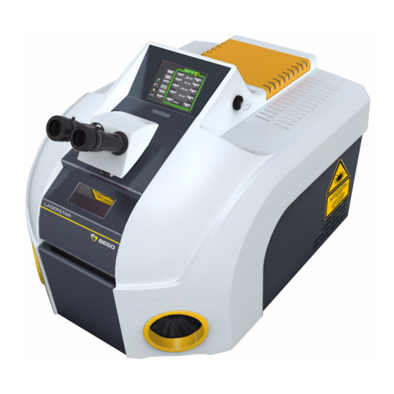
English ⋅ LaserStar T Plus System description Overall view Fig. 1 Overall view The Fig. 1 provides an overall view of the laser system when closed. The individual function elements are identified by capital letters and defined below. Touch screen... -
Page 15: Technical Data
English ⋅ LaserStar T Plus Technical Data Dimensions and weight Width x height x depth 540 x 460 x 690 mm (maximum) Weight (about) 60 kg Electrical data voltage - frequency - power 230 V - 50/60 Hz - 10 A (1 phase) - Page 16 English ⋅ LaserStar T Plus Display and operating elements EMERGENCY STOP button Main switch Fig. 2 EMERGENCY STOP button on the left side Fig. 4 Main switch on the rear side Key switch Fig. 3 Key switch on the right side...
- Page 17 English ⋅ LaserStar T Plus Touch screen Operating elements in the working cham- The main functions can be controlled by the operating elements on the console inside the working chamber. Fig. 6 Control elements in the working chamber Fig. 5 Main menu V–...
- Page 18 English ⋅ LaserStar T Plus Interlock circuit The LaserStar T Plus is equipped with a safety The laser shutter can only be opened when: circuit (Interlock circuit). • the working chamber door is closed, and This interlock circuit, together with the laser shutter, •...
- Page 19 English ⋅ LaserStar T Plus Main menu elements and their functions Display of status and error messages (in the example above: Working chamber door is open). Button: Open and close the shutter Display: Shutter status (for details SHUTTER STATUS DISPLAY) →...
- Page 20 English ⋅ LaserStar T Plus Shutter status display The current operating state of the laser shutter is (solid vertical bars symbolize that the laser beam is shown with the following symbols blocked) and colors. Unit is ready for operation. The laser shutter is not enabled and can not be opened.
- Page 21 English ⋅ LaserStar T Plus Alphanumeric input window Service menus The service menus are divided into four levels with The touchscreen shows a window with an alphanu- different access rights. meric keyboard if any numeric value for parameters or names for storage spaces or pulse shapes are to be entered (see following example).
- Page 22 English ⋅ LaserStar T Plus Service menu USER The indicated values represent the percentage for the respective events in relation to the defined thres- holds (for details see the following description). The [ Get ] button of the Sysinfo window opens the following window.
- Page 23 English ⋅ LaserStar T Plus History Service menu ENGINEER Fig. 13 Service-Menü Engineer-Ebene/Seite 1 Fig. 12 History Engineer level / page 1 The [ Get ] button of the SERVICE MENU USER → Having entered the engineer password the engineer opens the window to indicate the event logs.
- Page 24 English ⋅ LaserStar T Plus Lamp settings Lamp pulse counter The [ Reset ] button resets the counter to zero (after lamp replacement). It is recommended to confirm the replacement otherwise the system generates repeatedly inappro- priate maintenance recommendations. Lamp warn level...
- Page 25 English ⋅ LaserStar T Plus Engineer level/Page 2 Fig. 16 PSU test Fig. 15 Service menu - Engineer level / page 2 The [ Start ] button initiates a PSU test. The button text changes to [ Working ] on inverted background Change engineer password as long as the test is running.
- Page 26 English ⋅ LaserStar T Plus Diagnosis The [ Start ] button opens a window with several pages where the current status of all observed SHUTTER-I/O inputs and outputs are indicated. Depending on the system configuration not all listed inputs and outputs (see tables below) are active.
-
Page 27: Installation
English ⋅ LaserStar T Plus Installation This chapter contains a description of the prerequi- Ambient conditions sites for trouble-free operation of the system, as well • Temperature as instructions for setting up, starting up and trans- porting the device. Operation Ambient temperature - Full load: max. - Page 28 Make sure that the table has a load • 3 m protective gas hose bearing capacity of > 60 kg when • Digital pedal switch, double-stage setting up the LaserStar T Plus. • 2 Power supply cable (EU and USA/Japan) Unpacking • Fill tube with funnel The laser device has been tested thoroughly before •...
- Page 29 English ⋅ LaserStar T Plus Mounting the stereo microscope Fig. 22 Mounting the stereo mikroscope, Part1...
- Page 30 English ⋅ LaserStar T Plus Fig. 23 Mounting the stereo mikroscope, Part 2 The adjustment of the stereo microscope is described in the section ADJUSTING THE → STEREO MICROSCOPE.
- Page 31 English ⋅ LaserStar T Plus Filling up and connecting NOTE Connections The connections are on the rear side of the device. For damages to persons or property caused by improper connection of the device, warranty responsibility claims void. Fig. 24...
- Page 32 English ⋅ LaserStar T Plus First putting into operation After properly having finished all activities described If the self-test has been finished without an error in the section FILLING UP AND CONNECTING message, the device is ready for operation. →...
- Page 33 English ⋅ LaserStar T Plus Disassembling (preparation for trans- port) WARNING High weight! At least two people are needed to carry the device. To prepare the device for transport over minor distances you only have to unplug the power supply, the pedal switch and, if necessary, the inert gas supply.
-
Page 34: Operation
English ⋅ LaserStar T Plus Operation General instructions Workplace The following sections describe how to handle the The device is designed so that the operator can unit. The symbols and fonts used in the description easily reach all the necessary operating elements are explained in the section CONVENTIONS. - Page 35 English ⋅ LaserStar T Plus Visual inspection of the laser protective NOTE window The laser protective window should not have any Repeatedly turning the unit on and off causes a scratches, fractures, chips, cracks or discoloration. temperature-related delay of the laser firing since...
- Page 36 English ⋅ LaserStar T Plus Function test of the EMERGENCY STOP button Make sure that the laser has not been opera- Press the EMERGENCY STOP button to the ted for a few minutes before starting the test left of the stereo microscope.
- Page 37 English ⋅ LaserStar T Plus Enter the desired parameter value via the touchscreen keyboard (details → ALPHANU- MERIC INPUT WINDOW) and confirm the input with [ ↵ ]. The input window is closed and the entered value is indicated in the main menu.
- Page 38 English ⋅ LaserStar T Plus AUTO SAVE The current parameter setting in the main menu are automatically saved in this memory space as soon as a parameter set is loaded from the memory (with the buttons [ M– ] or [ M+ ] in the main menu or via the memory manager) or if the device is turned off.
- Page 39 English ⋅ LaserStar T Plus Retrieving and editing pulse shapes (pulse shape editor) Basics Pulse shape editor (Shape manager) The shape of the laser pulse (i. e., the time base of the intensity of the laser beam) has an essential...
- Page 40 English ⋅ LaserStar T Plus Change pulse shape To move a node, touch the respective node, drag it to the desired position and release it. Two concentrical red circles mark the cur- rently activated node (see Fig. 35). ...
- Page 41 English ⋅ LaserStar T Plus ECO-Modus settings Save pulse shape Touch the [ Save to ] button (in the pulse Basics shape editor). The activated ECO-Modus systematically turns off The pulse shape editor window is closed not required system components according to the and the prompt Save to...
- Page 42 English ⋅ LaserStar T Plus Switching inert gas on/off Setting workpiece illumination This button in the main menu activates / deactivates the inert gas supply. This button in the main menu opens the following If activated (button without the symbol ) the inert dialog for setting of the workpiece illumination.
- Page 43 English ⋅ LaserStar T Plus Turning off the system Fig. 38 Switches and Connector Panel Save entries (such as laser parameters, pulse shapes) that are not yet saved. Turn the LASER key switch (B) to the "0" posi- tion (C).
- Page 44 English ⋅ LaserStar T Plus Faulty operations This section describes common faulty operations of the laser system. Error description Possible cause Remedy The laser was not ignited. Temporarily turn the LASER key switch into START position. Display: immediately after turning on...
-
Page 45: Dental Instructions
English ⋅ LaserStar T Plus Dental instructions Basic instructions Planning the joint The aim of every welding operation must be to join The design of the denture must therefore be the workpieces together such that they can planned in advance and modelled in wax appro- priately. - Page 46 English ⋅ LaserStar T Plus Using welding wire Often the job is to weld the workpieces through and through into the inside. This is done by enlarging the seam to the centre and filling with welded-in wire as filler metal.
- Page 47 English ⋅ LaserStar T Plus BEGO filler metals for laser welding Alloy Recommended filler Order Alternative metal • High gold content, veneerable Bio PontoStar XL Bio PontoStar XL wire 61167 Bio PontoStar Bio PontoStar wire 61157 PontoStar G PontoStar G wire...
- Page 48 50008 direct butt joint possible Material thickness: BEGO precious metal wires 0.35 mm, Wiroweld 0.35 and 0.5 mm, Wiroweld NC 0.35 mm, titanium wire 0.35 mm. Important: If different alloys are welded together (e.g. combination technique), always use the nobler...
- Page 49 In these cases welding is successful with filler metal of BEGO's carbon- • charging voltage (the energy rises with the vol- free non-precious Wiroweld welding wire on a tage) and CoCrMo base.
- Page 50 English ⋅ LaserStar T Plus Fix ("bond") on the model Avoiding stress Since the laser weld must be executed on all sides When the seam is filled with filler metal, the with few exceptions and, moreover, the filler metal workpiece is heated locally, which is inevitably wire is fed manually, first the workpieces to be joined connected with stress.
- Page 51 English ⋅ LaserStar T Plus Case examples The varied options offered by the laser in providing solutions for dental welding work are described on the basis of examples below. The methods proposed can be applied analogously to many other welding tasks.
- Page 52 English ⋅ LaserStar T Plus In this welding operation the seam dips along its b) Precious metal to non-precious metal entire length in the gap due to the physical Prepare the two parts of the joint similar to a), tack processes during melting and rehardening.
- Page 53 English ⋅ LaserStar T Plus c) Titanium The parts must be ground appropriately for precise fitting in order to join titanium. If necessary, make adapters out of sprues or insert filler metal. Never anneal or grind the titanium too hot.
- Page 54 English ⋅ LaserStar T Plus Repairs and extensions Bar break and clasp break Building up contact points (build-up welding) In the case of non-precious metal and precious metal, grind the break points of the two parts to be Material is built up in layers using welding wire of the...
- Page 55 Pulse shapes The shape of the laser pulse (i.e. the curve of the The LaserStar T plus plus welding laser has four intensity of the laser beam over time) has a signi- fixed preset pulse shapes, which can be selected for...
-
Page 56: Status And Error Messages/Fault Clearance
English ⋅ LaserStar T Plus Status and error messages/ Fault clearance General information Status and error messages are displayed as In the table in the following section, this error classi- symbols at the top edge of the touchscreen. fication is referred to in the column Type by the symbol or the abbreviation IL. - Page 57 English ⋅ LaserStar T Plus Status / error messages, causes and remedy No. Symbol Type Meaning/Explanation Measures Completely close the working chamber Working chamber door not or not door. completely closed. If the symbol keeps on being indicated, ple- ase contact the service department.
- Page 58 English ⋅ LaserStar T Plus No. Symbol Type Meaning/Explanation Measures Shutter fault Please contact the service department. Switch the device off and on again several times, and note the time it takes for the Focus fault The entered value for...
-
Page 59: Service And Maintenance
18590 Pedal switch(electric) complete 18591 Fuse 16 A 18592 NOTE The following wear parts will not be replaced free of charge within the guarantee or the BEGO warranty. Optional equipment Name Quantity Filter system Ventus 26205 Pressure regulator for Argon inert gas... - Page 60 English ⋅ LaserStar T Plus Maintenance (care) The maintenance of the device reduces to the DANGER cleaning of the surfaces with a damp cloth with light Uncontrolled escape of laser alkaline solution. radiation! If there are holes in the leather cuffs or...
- Page 61 English ⋅ LaserStar T Plus Replacing the lens protective glass The protective glass prevents the lens from being damaged by mechanical influences as metal splashes or dust. In order to reduce power losses by absorption the protective glass is antireflection coated on both sides.
- Page 62 English ⋅ LaserStar T Plus Replacing the ring light protective glass Replacing the splash protection window If the device is equipped with the optional ring light, the protective glass on the ring light only needs to be replaced if it is defective or so dirty that the lighting provided is no longer adequate.
- Page 63 English ⋅ LaserStar T Plus Fig. 53 Allen screws/Rearside of the device Remove the 2 Allen screws at the rear of the device. The arrow in Fig. 53 shows the position of the screw on the left side (seen from behind).
- Page 64 English ⋅ LaserStar T Plus Checking/refilling the coolant In the cover on the rear of the device is a recess in which you can see the coolant level of the supply tank, and markings for the minimum and maximum permissible coolant level (see arrows in Fig. 54).
- Page 65 English ⋅ LaserStar T Plus Replacing the water filter Procedure Switch off the laser: Turn the Laser key switch Open and remove the closing cap of the water to "0" position and the main switch "0" position. filter insert (see arrow (B) in Fig. 56).
- Page 66 English ⋅ LaserStar T Plus Replaicing the air filter The device is equipped only with a simple air filter consisting of a filter fabric and a spark protection mat (see Fig. 58 and Fig. 59). Procedure Open the working chamber door.
- Page 67 English ⋅ LaserStar T Plus Setting combinations Focal Filler metal of Voltage Time Situation point the same type Ø necessary?* 1 Clasp break partial denture (Co-Cr) 2 Break in sublingual bar (PD) 3 Cavity in partial denture frame 4 Retentions (bent) to partial denture...
- Page 68 English ⋅ LaserStar T Plus Preassigned parameter values Memory Display Voltage Duration Focus Pulse location Application Ø shape* Clasp break PD Clasp break in partial denture Retentions to PD Partial denture retentions to partial denture PA to PD Precious-metal secondary...
-
Page 69: Marking
English ⋅ LaserStar T Plus Marking Warning signs and information signs All points where any danger might arise under certain circumstances (e.g. when safety covers are opened) are marked with the stipulated warning and explanatory signs. The location of the signs is shown in the following figures. - Page 70 English ⋅ LaserStar T Plus Fig. 66 Warning signs at power supply of lamp and Fig. 65 Warning and information signs on top of the excitation unit Device designation Fig. 67 Type plates...
-
Page 71: Disposal
Instructions for disposing of the device (Applicable only within the European Union.) The adjacent symbol on the ID plate of the BEGO device indicates that the device, in accordance with the European directive on waste electrical and electronic equipment, may not be disposed of as normal domestic waste. -
Page 72: Index
Handling deionised water (cooling water) 9 Basic Equipment 25 Harmful gases and vapors 9 Basic instructions 42 Hazard during normal operation 8 BEGO filler metals for laser welding 44 Hazardous areas 7 Blinding hazard 8 How to operate 17 Butt welding 49... - Page 73 English ⋅ LaserStar T Plus Pay attention to alloy composition 46 Warning signs and information signs 66 Personal protective equipment 7 Warranty and liability 5 Personnel qualification 8 Welding individual attachments 50 Planning the joint 42 What to do if you receive a bum 9...
- Page 76 BEGO Bremer Goldschlägerei Wilh. Herbst GmbH & Co. KG Technologiepark Universität · Wilhelm-Herbst-Straße 1 · 28359 Bremen Telefon +49 421 2028-0 · Telefax +49 421 2028-100 · E-Mail: info@bego.com...
Need help?
Do you have a question about the LaserStar T Plus and is the answer not in the manual?
Questions and answers