Table of Contents
Advertisement
Quick Links
Advertisement
Table of Contents

Related Manuals for IFM AC1401


Summary of Contents for IFM AC1401
- Page 1 Operating instructions AS-i Profinet gateway AC1401 / AC1402...
-
Page 2: Table Of Contents
Contents 1 Preliminary note ���������������������������������������������������������������������������������������������������4 1�1 Notes on this document ���������������������������������������������������������������������������������4 1�2 Symbols used ������������������������������������������������������������������������������������������������4 2 Safety instructions �����������������������������������������������������������������������������������������������4 2�1 General ����������������������������������������������������������������������������������������������������������4 2�2 Installation and connection ����������������������������������������������������������������������������4 2�3 Tampering with the device �����������������������������������������������������������������������������5 3 Functions and features ����������������������������������������������������������������������������������������5 3�1 Configuration interface X3 �����������������������������������������������������������������������������5 3�2 Fieldbus interface X6 and X7 ������������������������������������������������������������������������5 3�3 Electrical supply ���������������������������������������������������������������������������������������������5 4 Installation������������������������������������������������������������������������������������������������������������6... - Page 3 9�1 Data sheets �������������������������������������������������������������������������������������������������14 9�2 Programming manual ����������������������������������������������������������������������������������14 10 Maintenance, repair and disposal ��������������������������������������������������������������������14 11 Approvals/standards ����������������������������������������������������������������������������������������15 12 Scale drawing ��������������������������������������������������������������������������������������������������15...
-
Page 4: Preliminary Note
1 Preliminary note 1.1 Notes on this document This document applies to devices of the type „AS-i Profinet gateway“ (art� no�: AC1401 /AC1402)� It is part of the device and contains information about the correct handling of the product� This document is intended for qualified electricians� These specialists are people who are qualified by their training and their experience to see and to avoid possible hazards that may be caused during operation of the device�... -
Page 5: 2�3 Tampering With The Device
► Prevent metal foreign bodies from penetrating� 3 Functions and features The AS-i Profinet gateway includes one (AC1401) or two (AC1402) AS-i masters, one WEB server and a Profinet interface with 2-port switch� • It controls the exchange of data to the sensor / actuator level�... -
Page 6: Installation
5.1.1 Device supply via AUX, AS-i supply via AS-i power supply ► Supply the device with a voltage of 24 V DC (18���32 V PELV) (e�g� from the 24 V DN3011 power supply of ifm electronic)� The connection is made to the terminals X2�... -
Page 7: 5�1�2 Device And As-I Supply Via The As-I Power Supply
5.1.2 Device and AS-i supply via the AS-i power supply ► To supply the AS-i lines connect the terminals X1 to one or two AS-i power supplies (AC1401: one AS-i master, AC1402: two AS-i masters)� ► Ensure a low-resistance connection of the symmetry point of the device (terminal X1�5 FE) to the ground of the installation�... -
Page 8: 5�2 Wiring
Several gateways can be supplied by one powerful power supply� 5.2 Wiring Terminal X1 Combicon 5�08 Description AS-i 2 + AS-i + for AS-i line 2 AS-i 2 - AS-i - for AS-i line 2 AS-i 1 + AS-i + for AS-i line 1 AS-i 1 - AS-i - for AS-i line 1 Functional earth... -
Page 9: Operating And Display Elements
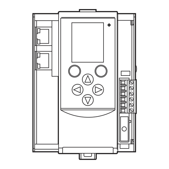
6 Operating and display elements 6.1 Operating elements 1: LEDs H1 2: LEDs H2 / H4 3: Profinet interface 2 (RJ 45) 4: Profinet interface 1 (RJ 45) 5: LEDs H3 / H5 6: Navigation buttons 7: Softkeys 8: Combicon connector... -
Page 10: 6�2 Led Displays
1: Slot for SD cards 2: Configuration interface (RJ45) 6.2 LED displays 6.2.1 Device LED H1 A diagnostic LED on the Profinet / AS-i gateway informs you of the state of the device and the connected systems� LED status Description The green LED is lit: >... -
Page 11: 6�2�3 Connection Leds H3 And H5
6.2.3 Connection LEDs H3 and H5 LED status Description The green LED is lit: Physical connection ok 7 Operation 7.1 Settings During operation the display is switched off after 10 minutes without operation� ► Activate the display by pressing any desired button� 7.1.1 Language selection ►... -
Page 12: 7�2 Navigation
7.2 Navigation 7.2.1 Navigation elements 1: User level 2: Focus 3: Operating area 4: Softkey labelling 5: Navigation compass 6: Navigation status bar 7: Main navigation bar 8: Info bar... -
Page 13: 7�2�2 Pictograms And Main Navigation
7.2.2 Pictograms and main navigation Quicksetup (Summary of the menu points required for a basic configuration) • Project all Projection adaptation for AS-i master 1 and AS-i master 2 (only AC1402) • Operating mode Selection of the operating modes for - AS-i master 1, - AS-i master 2 (only AC1402), - system (gateway, manual) -
Page 14: Diagnostics
9.1 Data sheets Data sheets can be found at www�ifm�com� 9.2 Programming manual The programming manual can be found at www�ifm�com� 10 Maintenance, repair and disposal ► Replace the buffer battery of the real-time clock as required, type CR2032 ► Dispose of the device in accordance with the national environmental... - Page 15 11 Approvals/standards The EC declaration of conformity and approvals can be found at www�ifm�com� 12 Scale drawing 106,2...
Need help?
Do you have a question about the AC1401 and is the answer not in the manual?
Questions and answers