Unic Stella di Caffe Technical Notes
Hide thumbs
Also See for Stella di Caffe:
- User manual (28 pages) ,
- Maintenance procedures (16 pages) ,
- Quick start manual (2 pages)
Table of Contents
Advertisement
Advertisement
Table of Contents
Troubleshooting

Related Manuals for Unic Stella di Caffe


Summary of Contents for Unic Stella di Caffe
- Page 1 NZ9009 02/15...
-
Page 2: Table Of Contents
1. SAFETY INSTRUCTIONS ............................. 5 2. IMPORTANT INFORMATION ..........................5 3. PRESENTATION OF THE STELLA DI CAFFE ......................6 ..............................6 S PTION TEAM D (DCL) ............................. 6 ONTROL PTION 4. FEATURES OF THE STELLA DI CAFFE ........................7 Unpacking the machine ............................ - Page 3 8. USE ................................32 D 45100) ......................32 OSAMAT CONTROL BOX PART NUMBER 2- : 45102) ....................32 CUP CONTROL BOX DOSE PART NUMBER 3- : 45103) ....................33 CUP CONTROL BOX DOSE PART NUMBER M (ON/OFF : 45101) ....................
- Page 4 11. STELLA PROGRAMME FLOWCHART ........................ 84 L 0: U ................................84 EVEL L 1: C ............................85 EVEL OFFEE SPECIALIST L 2: B ..............................86 EVEL ARISTA L 3: M ............................87 EVEL ANAGER L 4: T ..............................
-
Page 5: Safety Instructions
1. SAFETY INSTRUCTIONS - This machine is not intended to be used by persons (including children) with diminished physical, mental or sensorial capacities, or lacking in experience and savoir faire, unless they are supervised or have received training in the use of the machine from a person responsible for their safety. - Children should be supervised to ensure that they do not play with the machine. -
Page 6: Presentation Of The Stella Di Caffe
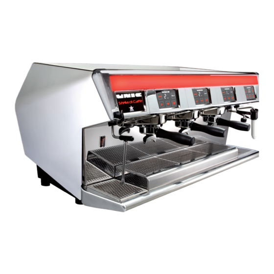
3. PRESENTATION OF THE STELLA DI CAFFE The Stella di Caffe has the advantage of having an independent boiler for each group, in addition to a large capacity steam boiler. All the machine operating settings can be viewed and adjusted simply and intuitively from the touch screen. -
Page 7: Features Of The Stella Di Caffe
4. FEATURES OF THE STELLA DI CAFFE The machine is delivered in a cardboard packing case and screwed to a wooden pallet. Unpacking the machine Cut the bands Open the box and take out the box holding the accessories... -
Page 8: Draining
Draining Tools required: Flat screwdriver - Pipe with a minimum inside diameter 15 mm: supplied with the machine Multigrip pliers To connect the drain pipe to the machine, it is necessary to remove the overflow tray (remove the overflow tray grids, unscrew the 2 knurled screws and pull the overflow tray towards you) and the drain connection fixing screws. -
Page 9: Heck The Toroidal Transformer In Relation To The Mains Voltage
Check the toroidal transformer in relation to the mains voltage The machine is fitted with a multi-voltage transformer to ensure that the supply to the electronics is at the right voltage. The machine is factory set according to its country of destination. E.g.: If it is necessary to change the factory setting, only the jumpers should be repositioned: no wiring should be moved. -
Page 10: Filling The Boilers
Filling the boilers As soon as the power is switched on the boilers fill automatically. Remember to turn on the water stop valve. Steam boiler A safety function is provided in case the boiler is not filled in within 3 minutes: the filling solenoid valve and the pump switch off. -
Page 11: Inspection And Adjustment
Inspection and adjustment Tool required: 2.5 mm Allen key Normally all adjustments are made before the machine leaves the factory. Check that these adjustments are correct and change them if necessary; proceed as follows to access them: You need to remove the right side panel of the machine: Remove the screws next to the cup warmer and pull the side panel towards the back to remove it. -
Page 12: Adjusting The Pump Pressure
Adjusting the pump pressure The pump is on the right side and is adjusted from the same side. During infusion the pressure should be between 8 and 9 bars (displayed on the control / adjustment screen). Turn the adjustment SCREW IN to increase the pressure Turn the adjustment SCREW OUT to reduce the pressure Tools required: Flat screwdriver... -
Page 13: Interface
6. INTERFACE Menu description Codes: for accessing the various levels of the menu Settings: for use or setting of: date and time, language, sound, screen background, group and lighting. User: for use or setting of the following functions: rinsing, cleaning groups, coffee counters, programming maintenance, light bar on / off and water softener. -
Page 14: Browsing The Menu
Browsing the menu The icons below represent all the browsing functionalities of the STELLA menu. Menu title Return to the Confirmation previous after menu programming Increase a value Equalize all Scroll the values up or down Reduce a value Select a group to make an adjustment to it Switch from one menu to... -
Page 15: Programming
7. PROGRAMMING Codes (levels 1, 2 and 3) Most of the menus are locked out by default. Adjustment and programming are impossible. Access to the adjustments is authorised by entering a code with three access levels. For more information refer to the chapter entitled: "Stella programme tree structure". -
Page 16: Settings
Enter the new level access code twice Settings Date & Time (levels 1, 2 and 3) To adjust the date and the time Use the + and – keys to adjust the desired value. When you select a value to make an adjustment, it turns pink. -
Page 17: Sound (Levels 1, 2 And 3)
Sound (levels 1, 2 and 3) To activate or de-activate the sound and adjust the volume Wallpaper (levels 1, 2 and 3) The screen background can be an image / photograph or a display of the machine settings. Displays the programmed temperature and the actual temperature of each unit. -
Page 18: Light Bar Backlighting And Keyboards (Levels 1, 2 And 3)
Confirm the adjustment to View the wallpaper and confirm the wallpaper by pressing it save the settings. Importing a screen background: • Before importing a screen background insert the USB dongle in the side of the machine. • The USB dongle and the images must be correctly configured for the machine to read them. Contact your dealer for more information. -
Page 19: Machine Adjustment
Colour Value White Yellow Green Cyan Blue Pink Machine adjustment (level 1, 2 and 3) For making the adjustments specific to the coffee machine: temperature, dosing, pressure, etc… Group adjustment (level 1, 2 and 3) To adjust and view the temperatures of the groups, the pre-infusion, the self time and the doses. -
Page 20: Temperature Adjustment (Level 1, 2 And 3)
Temperature adjustment (level 1, 2 and 3) To adjust the temperature of each group. Programmed temperature. – Use the keys to adjust the desired value. Confirm the adjustment to save the settings. Actual temperature (sensor). Select the group. ... -
Page 21: Pre-Infusion Adjustment (Levels 1, 2 And 3)
If the MAN key is not lighted, press it (Only on DOSAMAT machines); Engage the desired filter holder, e.g.: 1T, 2T or 3T In this case, the two-cup When the desired dose of filter holder is engaged. coffee is reached stop the Press small or large dose infusion with... - Page 22 (T2) The "closed" pre-infusion time is the time during which the solenoid valve remains closed. Use the + and – keys to adjust the desired value. Adjustment range: 0.1sec to 10sec √ Press to Confirm the adjustment to save the settings. If either of the two settings is adjusted to 0, the pre-infusion mode remains disabled.
-
Page 23: Self Time Adjustment (Levels 1, 2 And 3)
Self time adjustment (levels 1, 2 and 3) Only for DOSAMAT machines. Activating the timer delay makes it possible to place the cups in the SELF mode before the automatic cycle starts. Use the + and – keys to adjust the desired value. Adjustment range: 0 to 10 sec, default setting, 1 cup: 1.5 seconds ... -
Page 24: Steam Air
& hot water adjustment (levels 1, 2 and 3) team To adjust the settings of the team or the hot water control box: the temperature at the steam wand probe (only on machines with team the steam timer the hot water volumes When you select a line to make an adjustment, it turns pink. -
Page 25: Iscellaneous Levels
Miscellaneous (levels 1, 2 and 3) To activate the timer function and assign dose priority to the starting of a cycle: small dose, large dose, last dose used (Only on DOSAMAT machines) To adjust dose priority at the start of a cycle: adjust timer display on the display of... -
Page 26: Continuous/Stop Cycle Key
Continuous/stop cycle key Existing functions: 1. Stop an infusion in progress 2. Start a continuous cycle (without dosing) manually 3. Extend a dose manually at the end of a cycle. 4. To have a 3 programmable cup volume (volumetric), when the cycle is started with the continuous key. - Page 27 For a machine with the Dosamat system, functions 4 (3rd dose) and 5 (Barista rinsing) will be compatible. The distinction will be made by the presence of the filter holder: With the filter holder engaged = 3 dose / without filter holder = Barista rinsing. Function 4 = 3rd dose: “Continuous key = 3 dose"...
-
Page 28: Counter
In all events: The "continuous" key can stop a cycle that is running at any time, and should remain lighted during cycles, and also can be used at the end of the cycle to allow the dose to be extended. The 150 second safety limit is also maintained. - Page 29 - Counter visible level 0 (YES / NO): to display or mask the reading of counters in level 0. - Reset of all counters: Serves to reset all counters in a single operation (total reset of small doses, total reset of large doses, total reset of continuous/stop, total reset of steam, total reset of water doses).
- Page 30 Reset of counters (level 3 and USB level only): When consulting counters by level 3 or USB level the RAZ indication appears on the total counter line and the partial counter line; this indicates that it is possible to reset the counters. Reset possible indicator The reset is performed by pressing the line To confirm the reset press YES twice...
- Page 31 Total per Counter: ACTION Total reset Partial reset group A- Small + large "coffees" + continuous B-Small "coffee” C-large "coffee” TOTAL reset D-Continuous/stop Total per Counter: ACTION Total reset Partial reset group A- Small + large "coffees" + continuous B-Small "coffee” C-large "coffee”...
-
Page 32: Use
8. USE Dosamat control box (part number 45100) 1 2 3 • The figures correspond to the filter holder engaged (1, 2 cups or 3 cups) • keys correspond respectively to the selection: (small dose) , or (large dose) •... -
Page 33: Cup Control Box Dose Part Number : 45103)
• The continuous/stop key can be used: • to stop a cycle in progress • to start a continuous cycle (not dosed) • A brief pressure at the end of the cycle also triggers the display of the infusion time if the time function has been activated, except during the pre-infusion time. -
Page 34: Manual Control Box (On/Off Part Number: 45101)
Manual control box (ON/OFF part number: 45101) • The display shows the infusion time Cycle start Cycle stop control box (part number 45104) team • The display shows the volume of the water dose, the steam timer or displays the actual temperature of the team sensor, depending on the cycle in progress. -
Page 35: Steam Air Option
Hot water/manual tap control box (part no 45105) • The display shows the progress of the programmed water dose • keys correspond respectively to the programmed small and large water doses. • key stops the cycle in progress and enables a continuous non-dosed cycle to be started. -
Page 36: Dual Control Option (Dcl)
Dual Control Option (DCL) Serves to control infusion and pre-infusion manually The group control box remains fully operational. A pressure gauge indicates the instant pressure in the group's pre-infusion chamber When the dual control in use the keyboard is disabled and vice versa The system is fitted with a detent enabling the engagement of the pre-infusion solenoid valve to be felt on the handle Keyboard compatible with the dual control system... -
Page 37: Cleaning And Maintenance
9. CLEANING AND MAINTENANCE After every use Steam outlet pipe: After every use, clean the steam outlet pipe with a damp cloth and blow steam out briefly to remove milk residue from the inside of the pipe Daily ... - Page 38 The BTA indicates: Description of the cleaning cycle: -Sequences of 8 seconds ON and 12 seconds OFF (EVX+PUMP) -Numbers of sequences: (les BGX indiquent le nombre de cycles restants) During the cleaning cycle: Phase Display Disabled, steady blue on the control Selection of groups on the “Gn”...
-
Page 39: Semi-Automatic Rinsing
- The progress bar (blue) increases every 30sec - The progress bar display is controlled by the last group started. - At the end of the cleaning cycle, the control boxes and the luminous strip above the control boxes are illuminated steady blue. - Page 40 Description of the cycle end: Step 5 The BTA indicates: The BGX control boxes are blue for 2 seconds and then return to display and normal operation. The BTA displays the message above for 5 seconds and then returns to normal display Important: Once the groups have been selected and confirmed (step 2) it is no longer possible to exit from the cleaning mode, the home key disappears.
-
Page 41: Weekly
Weekly In addition to daily cleaning: Portafilter: Remove the filter basket and clean the cup and basket with soapy water. Overflow tray: Remove the top of the ball and clean it underwater. Front panel cleaning The front panel cleaning mode disables all the touch keys to allow them to be cleaned. Press the broom-shaped icon until the control boxes display "nC". -
Page 42: Leaning The
Cleaning the team outlet Remove and clean the outlet at least once per day After every use, rinse the outlet by blowing steam out BEFORE 2012 AFTER 2012 Others Use a soft cloth and alcohol to clean the stainless steel parts and nonabrasive cleaner for the painted parts of the machine. -
Page 43: Maintenance And Repairs
10. MAINTENANCE AND REPAIRS Calibration procedure of BTA The calibration allows to adjust the screen surface and sensitivity of the screen support. To perform the procedure, - insert the USB key (the sand clock appears, and then upgrade screen). - Check only «... -
Page 44: Update Procedures
Update procedures During an update you should: - If possible save the machine settings on the machine USB dongle (Maintenance data transfer settings export - Perform an update of the CPU with a USB+ dongle - Import the CIM configuration from the machine USB dongle (Maintenance data transfer CIM import ) or reconfigure the machine using CIM creator - Import the machine configuration (Maintenance ... -
Page 45: Bgx/Bst Update
Press "upgrade" a second time The BTA displays the evolution of the update and the status of each control box. The colour orange shows that the update is in progress, the colour green confirms success of the update, and red indicates that the update has failed. -
Page 46: Assignment Of One Or More Bgx/Bst Control Boxes
Assignment of one or more BGX/BST control boxes If a mistake is made when assigning one or more control boxes it is possible to re-launch the assignment process. Start the machine and wait for the end of the BTA starting cycle At the end of the starting cycle insert the USB + dongle The hourglass pointer appears, followed by the improvement screen Uncheck "Calib"... -
Page 47: Using Cim-Creator
Using CIM-creator This can be used to configure the equipment such as control boxes and various outputs. Prerequisite: to use CIM-creator you need to possess a machine updated with a BTA V2 and a USB + dongle Insert the USB+ dongle Click on cancel Click on maintenance You are now in CIM Creator... - Page 48 Standard type settings: 2 units SDC with Dosamat (DM) box 3 units SDC with 6 doses (3cups) team (ST) box And hot water (HW) box Don't check the DC boxes (unless option DCL) 3 units SDC with manuals (ON/OFF) box 3 units SDC with 4 doses (2cups) box And Hot water (HW) And hot water (HW) box...
-
Page 49: Iagrams
Diagrams BGX control box connections... -
Page 50: Bta & Bst Control Box Connections
BTA & BST control box connections... -
Page 51: Cpu Board Connections
CPU board connections... -
Page 52: Lights And Straps
Lights and straps JUMPER DESIGNATION DESCRIPTION Alimentation pressostat CPR +12V/+5V CPR pressure switch supply +12V / +5V Alimentation pressostat STV +12V/+5V STV pressure switch supply +12V / +5V STV NTC / pressure switch sensor Préparation capteur STV NTC/pressostat preparation Alimentation rétroéclairage TFT 24V/15V TFT backlight supply 24V / 15V N.U. -
Page 54: Hydraulic Diagram
Hydraulic diagram E.g. Stella 3GR diagram ID-75 TUBE FLEXIBLE COUDE ARNE INOX FLEXIBLE PIPE NZ6015 TUBE EVACUATION SOUPAPE HP HP VALVE DRAIN TUBE NZ6016 TUBE EVACUATION SOUPAPE HP (V+) HP VALVE DRAIN TUBE (V+) NZ6011 TUBE REMPLISSAGE CHAUDIERE BOILER FEEDING PIPE NZ6008 RAMPE DOSEUR ET ENTREE EAU WATER FEEDING &... -
Page 56: Fuses
Fuses 24V BOARD FUSE, T1AL 250V 43113 24V BGX FUSE, F10AL 250V 43114 PUMP FUSE, 5TT5A 125V 43115 SWITCH FUSE, T2AL 250V 43116 PHASE FUSE, T1AL 250V 43113... -
Page 57: Wiring Diagrams
Wiring diagrams... -
Page 60: Itting Replacement Procedures
Fitting / replacement procedures When replacing a CPU you should: - If possible save the machine settings on the machine USB dongle (Maintenance data transfer settings export - Replace the faulty CPU by a new one - Perform an update of the CPU with a USB+ dongle - Import the CIM configuration from the machine USB dongle (Maintenance ... -
Page 61: Bta/Bgx/Bst Control Box Replacement
Tools required: Flat screwdriver Philips screwdriver, PZ1 BTA/BGX/BST control box replacement Switch the machine off Loosen the two screws (A) under the side grilles of the cup warmer, by approximately 1 cm, and free the front panel from the hooks by pushing the screws towards the back Tilt the front panel forward to gain access to the wiring Disconnect the connectors connecting the front panel to the machine to remove it. - Page 62 Loosen the screws holding the top of the panel (B) sufficiently to remove it Remove the strip Remove the white steel baffle plate to gain access to the screws holding the cheeks on the sides of the front panel Disconnect all the connectors from the control box to be changed and remove its four screws. Also loosen the screws holding the adjacent control boxes to leave enough clearance to be able to take the out the control box to be changed (on a BST or BTA loosen the cheek) Position the new control box and screw up the other control boxes...
-
Page 63: Fitting The Long Feet
Fitting the long feet Tools required: Flat screwdriver Rear feet (all versions) 12mm open end spanner or 8mm Allen key 7mm open end spanner Fit the 2 M6x35 screws (4) to the rear foot base (3). Position the long foot (1) on the chassis (1) Fix the foot to the chassis with the guide pin screw (2) Fix the base and its 2 screws under the foot with the M8x20 screw (6) Position the rubber foot (5) on the base... -
Page 64: Front Feet (V+ Version)
Front feet (V+ version) Assemble the front foot base (7) with the M4x16 screws (5). Take care to fit the shiny face to the top for the visible spacer Fit the M6x50 overflow tray mounting screw (9) with its spacer(s) (1x 2mm or 2x 1mm) (10) in the foot (1), positioning it towards the inside of the machine Position the long foot (1) on the chassis (1) -
Page 65: Troubleshooting
Troubleshooting List of fault codes for the technician FAULT CONDITIONS FOR EXIT COMPONENTS CONCERNED POSSIBLE CAUSES CONSEQUENCES CODE OF THE SECURITY No filling or cycle possible ABSENCE of mains water pressure or tank No heating of coffee Mains water pressure Automatic if fault empty: boilers if level sensors,... - Page 66 FAULT CONDITIONS FOR EXIT COMPONENTS CONCERNED POSSIBLE CAUSES CONSEQUENCES CODE OF THE SECURITY disconnected, absence of signal: Automatic if fault Doser, GROUP 1 Manual dosing alarm - Check the sensor and the wiring eliminated short circuit: Automatic if fault Doser GROUP 1 Manual dosing alarm - Check the component and the wiring eliminated...
- Page 67 FAULT CONDITIONS FOR EXIT COMPONENTS CONCERNED POSSIBLE CAUSES CONSEQUENCES CODE OF THE SECURITY Heating stopped on Group Reading outside the authorised range: Thermostat sensor, Automatic if fault - Check the programmed value and the GROUP 3 eliminated Control box BG3 on stand- sensor.
- Page 68 FAULT CONDITIONS FOR EXIT COMPONENTS CONCERNED POSSIBLE CAUSES CONSEQUENCES CODE OF THE SECURITY DOSAMAT sensor, disconnected, absence of signal: Automatic if fault Manual start alarm GROUP 4 - Check the sensor and the wiring eliminated DOSAMAT sensor, short circuit: Automatic if fault Manual start alarm GROUP 4 - Check the component and the wiring...
- Page 69 FAULT CONDITIONS FOR EXIT COMPONENTS CONCERNED POSSIBLE CAUSES CONSEQUENCES CODE OF THE SECURITY Alarm - Sensor reading not accepted - Pressure Reading outside the authorised range: Pressure sensor, Automatic if fault set point replaced by timer - Check the programmed value and the GROUP 3 eliminated sensor.
- Page 70 FAULT CONDITIONS FOR EXIT COMPONENTS CONCERNED POSSIBLE CAUSES CONSEQUENCES CODE OF THE SECURITY Fuse no 1 Broken ABSENCE OF SUPPLY 230 V ~ Fuse no 2 Broken ABSENCE OF SUPPLY 24 V Fuse no 3 Broken ABSENCE OF SUPPLY 12 V Fuse no 4 broken ABSENCE OF SUPPLY 5 V Fuse no 5 broken...
-
Page 71: Troubleshooting
Troubleshooting VERY IMPORTANT Before starting any action check that all the settings are correct Temperature 120 °C – steam pressure 0.9 to 1 bar (14PSI) Infusion pressure 9 to 10 bar (140 PSI) The HP valve opens for values over 13 bar (188PSI) Supply pressure: 0 to 6 bar (0 to 90 PSI) If the machine use water in a tank, check the tank level and the cleanliness of the foot valve /strainer if one is fitted... -
Page 72: Individual Test Procedure For Internal Components
Individual test procedure for internal components This enables you to check the operation of the components Menu → Settings → Component tests Insert the USB dongle and click on Settings. Component tests Click on The following screen appears: A. Group: Component code Component name Line action... - Page 73 Selection of group: Press = component on for max. 5sec Release = component off Press= pump solenoid valve of group (EVx) on for 10 sec (see detail) It is possible to stop the cycle by pressing the key again (modif. of 30/01/13) During the test, the display...
- Page 74 B. Machine Component code Component name Line action Press = component on for Switch max. 5sec (If it is possible) Release = component off Pump Filling solenoid valve ditto RSV1 Solid-state steam relay1 ditto RSV2 Solid-state steam relay2 ditto RSV3 Solid-state steam relay3 ditto Steam solenoid valve...
- Page 75 Press= water solenoid valve (EVE) on for 10 sec (see detail) It is possible to stop the cycle by pressing the key again (modif. of 30/01/13) During the test, the display counts down from 10 sec. The display increments the seconds and the pulses, and holds the display at the end of Total pulses of the...
-
Page 76: Cooling
Cooling To use the cooling function, go into maintenance → cooling → select the groups; a cycle of 100 seconds starts, execute 3 cycles of 100 seconds to cool a group. Computer system Insert the USB+ dongle Click on cancel Click on maintenance Click on CIM Click on external connections... - Page 78 WITH INTERFACE Pt no 45360 JP8=12V CN13...
- Page 79 WITHOUT INTERFACE Pt no 45360 JP8=12V CN13...
- Page 80 Note: the coffee machine is only usable when the badge contact is closed. To simulate the presence of the badge it is possible to connect points 33 and 35 of connector CN7 of the main interface. For the machine to work without the I/O interface, either connect points 2 and 3 of cable part no: NZ8018 or make a strap between points 2 and 3 of connector CN13 (red).
-
Page 81: Debit - Credit System
Debit – Credit system Code = code sent by the machine to the IO-32 board (or to the payment system) RL = active relay on the IO-32 board Type of control Cup volume or dose Code Code Code Code Code Manual (ON/OFF) 1 small... -
Page 82: Credit - Debit System And Rs232
Credit – Debit system and RS232 Type of control Cup volume or dose Code Code Code Code Code Manual (ON/OFF) 1 small 2 small 2 cups 1 large 2 large 1 small 2 small 3 small 3 cups 1 large 2 large 3 large 1 small... -
Page 83: System Information
System information Machine maintenance counter: The machine maintenance counter is only accessible via the USB dongle; press Maintenance > CIM > Information: It enables us to view: The total of all coffees (small, large and continuous) The total of all coffees per group (small, large and continuous) The servings total of hot water The servings total of steam and team... -
Page 84: Stella Programme Flowchart
11. STELLA PROGRAMME FLOWCHART Level 0: User The dotted lines represent the main menu... -
Page 85: Evel Offee Specialist
Level 1: Coffee specialist The dotted lines represent the main menu. Direct Access... -
Page 86: Evel Arista
Level 2: Barista (If installed in the machine) Direct Access The dotted lines represent the main menu. -
Page 87: Oss
Level 3: Manager / Boss The dotted lines represent the main menu. Direct Access... -
Page 88: Evel Echnician
Level 4: Technician USB dongle level The dotted lines represent the main menu. Direct Access... -
Page 89: Appendices
12. APPENDICES Setting values readings: Date: ../…../….. Customer: Machine number: SDC……………… Programme version: BTA: ….. CPU: ….. BGX: ….. Before any major update note the values in the menus below:... - Page 91 MEMO __________________________________________________________________________________ __________________________________________________________________________________ __________________________________________________________________________________ __________________________________________________________________________________ __________________________________________________________________________________ __________________________________________________________________________________ __________________________________________________________________________________ __________________________________________________________________________________ __________________________________________________________________________________ __________________________________________________________________________________ __________________________________________________________________________________ __________________________________________________________________________________ __________________________________________________________________________________ __________________________________________________________________________________ __________________________________________________________________________________ __________________________________________________________________________________ __________________________________________________________________________________ __________________________________________________________________________________...
- Page 92 __________________________________________________________________________________ __________________________________________________________________________________ __________________________________________________________________________________ __________________________________________________________________________________ __________________________________________________________________________________ __________________________________________________________________________________ __________________________________________________________________________________ __________________________________________________________________________________ __________________________________________________________________________________ __________________________________________________________________________________ __________________________________________________________________________________ __________________________________________________________________________________ __________________________________________________________________________________ __________________________________________________________________________________ __________________________________________________________________________________ __________________________________________________________________________________ __________________________________________________________________________________ __________________________________________________________________________________...
- Page 93 __________________________________________________________________________________ __________________________________________________________________________________ __________________________________________________________________________________ __________________________________________________________________________________ __________________________________________________________________________________ __________________________________________________________________________________ __________________________________________________________________________________ __________________________________________________________________________________ __________________________________________________________________________________ __________________________________________________________________________________ __________________________________________________________________________________ __________________________________________________________________________________ __________________________________________________________________________________ __________________________________________________________________________________ __________________________________________________________________________________ __________________________________________________________________________________ __________________________________________________________________________________ __________________________________________________________________________________...
Need help?
Do you have a question about the Stella di Caffe and is the answer not in the manual?
Questions and answers