Table of Contents
Advertisement
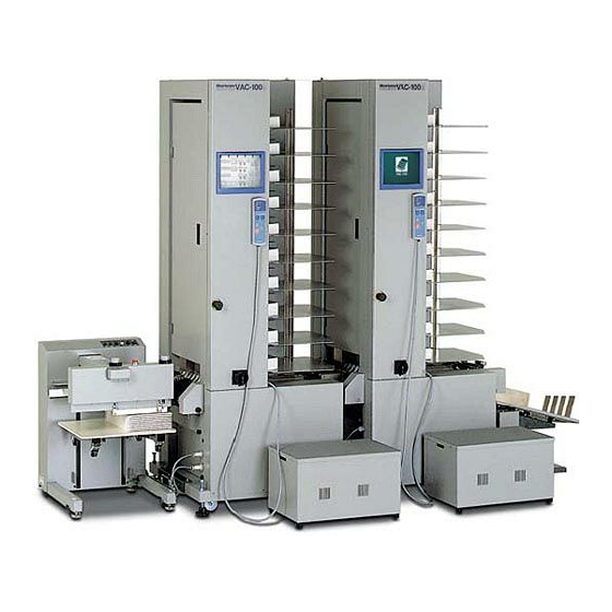
COLLATOR
- This manual is designed to help you to install, operate and maintain Collator, VAC-100.
Read, understand and keep this manual in a safe and convenient place.
- Do not operate VAC-100 until you read and understand the instructions in this manual.
- Horizon International Inc. shall not be liable for incidental consequential damages
resulting from : improper or inadequate maintenance by customer; unauthorized modifica-
tion or misuse; operation outside of the environmental specifications for the product.
- Horizon International Inc. pursues a policy of continuing improvement in design and
performance of the product. Therefore, the product design and specifications are subject to
change without prior notice and without our legal obligation.
- All rights are reserved. No part of the manual may be photocopied, reproduced or
translated to another language without the prior written consent of Horizon International Inc.
020702/VAC100/09E/DV
Important Information
VAC-100
I
UM201050-09
Advertisement
Table of Contents

Related Manuals for Horizon Fitness VAC-100


Summary of Contents for Horizon Fitness VAC-100
- Page 1 COLLATOR Important Information - This manual is designed to help you to install, operate and maintain Collator, VAC-100. Read, understand and keep this manual in a safe and convenient place. - Do not operate VAC-100 until you read and understand the instructions in this manual.
- Page 2 Safety Precautions - The signal word WARNING indicates a potentially hazardous situation which, if not avoided, could result in death or serious injury. - The signal word CAUTION indicates a potentially hazardous situation which, if not avoided, may result in damage on machines. It may also be used to alert against unsafe practices.
-
Page 3: Table Of Contents
CONTENTS Important Information .................... I Safety Precautions ....................II 1. Before You Begin 1-1 Specifications ...................... 2 1-1-1 VAC Series Specifications ................2 1-1-2 Receiving Tray (Option) Specifications ............3 1-2 Machine Descriptions ..................4 1-2-1 Overview ......................4 1-2-2 Feed Section ....................5 1-2-3 Operation Panel .................... - Page 4 2-2-6 Double Feed Stop Plate Height Adjustment........... 33 2-2-7 Separate Nose Adjustments ................33 2-2-8 Delivery Section Setup ................... 34 [1] Bulging Nose and Delivery Roller Setup ............34 [2] Weight Setup ....................35 [3] Delivery Air Adjustment ................36 2-2-9 Tray Unit Setup ....................37 [1] When CCR or CCR-DX Is Used ..............37 [2] When ST-20/ST-20R Is Used ................40 2-2-10 Setup in Main Page..................
- Page 5 4. Maintenance 4-1 Daily Cleaning ....................68 4-1-1 Feed Ring .......................68 4-1-2 Transport Belt ....................69 4-2 Monthly Cleaning ....................70 4-2-1 Bin Sensor ......................70 4-2-2 Delivery Sensor ....................70 4-3 Double Feed Stop Plate Replacement ..............71 4-4 Feed Error Sensor Cleaning ................72 5. Move and Installation 5-1 Collator Installation ...................74 5-2 Blower Box Installation ..................75 5-3 System Switch Set Up ..................77...
-
Page 7: Before You Begin
1. Before You Begin 1. Before You Begin 1-1 Specifications ................... 2 1-2 Machine Descriptions ................4 1-3 Accessories ....................22 1-4 Consumables and Options ..............24... -
Page 8: Specifications
1. Before You Begin 1-1 Specifications 1-1-1 VAC Series Specifications Module Type VAC-100a (Main Module) VAC-100m (Extension Module) VAC-100c (Rear Delivery Module) Number of Bins 10, 20, 30, 40, 50, 60 Sheet Size 148 x 148 mm to 350 x 500 mm (5.8"... -
Page 9: Receiving Tray (Option) Specifications
Min. Sheet Height 80 gsm (21.3 lb) 1 sheets (0.1 mm) The HMU-100 can be used with maximum of two-tower VAC-100. The HMU-100 can not be connected with c-tower VAC-100. The machine design and specifications are subject change without any notice. -
Page 10: Machine Descriptions
(option) can be connected as This unit is used to insert a sheet finishing device. on or under the collated sheets in VAC-100. It can be attached to a - Delivery Section tower or m-tower. Sheets are transported from this section to Accessories (Option) the accessory. -
Page 11: Feed Section
1. Before You Begin 1-2 Machine Descriptions 1-2-2 Feed Section Feed Rotor This rotor sucks and feed sheets. Feed Height Adjust Lever Feed Height Sensor (White) This sensor determines the This lever is used to adjust the sheet feed height. height of feed height sensor. -
Page 12: Operation Panel
1. Before You Begin 1-2 Machine Descriptions 1-2-3 Operation Panel [1] Main Page Tabs These tabs are used to select the page Error Monitor Button on the screen. This button is used to indicate feed error. Total Counter Delivery Air ON/OFF But- This counter counts sets of collated sheets. - Page 13 1. Before You Begin 1-2 Machine Descriptions Feed Speed Indication Feed speed can be set with triangle buttons below. The speed can be changed during opera- tion. Automatic Setup Button This button is used only when SPF-20A is combined. When this button is pressed, the collator speed is adjusted automatically to match the SPF-20A speed.
-
Page 14: Set 1 Page
1. Before You Begin 1-2 Machine Descriptions [2] Set 1 Page Tower Indication The current used towers (collators) are highlighted. Finishing Device Button This button is used to select the finishing device combined. When CCR-DX is used, CCR- DX icon must be selected. The standard icon ( ) must be used for all the other devices. -
Page 15: Set 2 Page
1. Before You Begin 1-2 Machine Descriptions [3] Set 2 Page Individual Calibration Buttons These buttons are used to calibrate the sheet thickness in the individual tower. All Tower Calibration Button This button is used to calibrate the sheet thickness in all towers. Sensor Button Page UP/DOWN Button This button is used adjust feed... -
Page 16: Program Page
Double Cycle : The VAC-100 system is divided into two sections. When any bin empties, the VAC-100 immediately switches over to the second section and continues collating. 1 Tower... -
Page 17: Memory Page
1. Before You Begin 1-2 Machine Descriptions [5] Memory Page Job No. Button Up to nine collating setup patterns can be stored with these buttons. Write Button Current Setup Button This button is used to memo- This button is used to indicate rize the collating setup pattern the current setup condition of in the selected job No. -
Page 18: Preset Input Page
1. Before You Begin 1-2 Machine Descriptions [6] Preset Input Page The preset input page is shown by pressing preset button on the main page or program page. UP Key This key is used to increase the number indicated. DOWN Key This key is used to decrease the number indicated. -
Page 19: Remote Controller
1. Before You Begin 1-2 Machine Descriptions 1-2-4 Remote Controller Trouble Monitor When collating operation stops, this monitor let the operator know the cause with lamp lighting. Speed Button This button is used to adjust the collating speed. The speed can be adjusted during the operation. This button has the same function as the one on 1 2 3 the main page. -
Page 20: Receiving Tray (Ccr)
1. Before You Begin 1-2 Machine Descriptions 1-2-5 Receiving Tray (CCR) Delivery Rollers Tray These rollers transport collated Tray for A5 to A4 sheet size or sets to receiving tray. Weights for B4 to A3 sheet size can be correct sheet skew. selected. -
Page 21: Receiving Tray (Ccr-Dx)
1. Before You Begin 1-2 Machine Descriptions 1-2-6 Receiving Tray (CCR-DX) Delivery Rollers Tray These rollers transport collated Tray for A5 to A4 sheet size or for B4 sets to receiving tray. Weights to A3 sheet size can be selected. correct sheet skew. -
Page 22: Stacker (St-20)
1. Before You Begin 1-2 Machine Descriptions 1-2-7 Stacker (ST-20) Delivery Rollers Stopper Adjust Knob These rollers transport collated This knob is used to adjust stop- sets to receiving tray. Weights per according to the sheet size. correct sheet skew. This knob can be locked with top knob on this knob. -
Page 23: Stacker (St-20R)
1. Before You Begin 1-2 Machine Descriptions 1-2-8 Stacker (ST-20R) Emergency Stop Button Stopper Adjust Knob This knob is used to adjust stopper according to the sheet Side Guide Adjust Knob size. This knob can be locked This knob is used to adjust side with top knob on this knob. -
Page 24: Stacker (St-40)
1. Before You Begin 1-2 Machine Descriptions 1-2-9 Stacker (ST-40) Stopper A Adjust Knob This knob is used to adjust stopper Feed Error Tray A according to the sheet size. The All errored sets are Feed Error Lamp A knob can be turn-locked into delivered to this tray. -
Page 25: Stacker (St-60)
1. Before You Begin 1-2 Machine Descriptions 1-2-10 Stacker (ST-60) Feed Error Tray All errored sets are delivered to this tray. Side Guide B This guide moves up Transport Unit and down every cycle Collated sets are transported to side B for off-set receiving. - Page 26 1. Before You Begin 1-2 Machine Descriptions (Operation Panel A) Single Motion Button The movable side guide Counter Button Counter Input Button can be actuated with This button is used to select this button. the mode of the counter. For further information, refer to 2-3.
-
Page 27: Hand Marry Unit (Hmu-100)
Sheets to marry are placed on the table. Sheet Guide This guide is set according to sheet width. Insert Mode Selecting Switch This switch is used to select the mode to insert a sheet on or under collated sheets from VAC-100 or to be off. -
Page 28: Accessories
1. Before You Begin 1-3 Accessories Connecting Plate (A920112-00) Detector (A924699-00) a:1 pc m:1pc c:1 pc Connecting Plate (A920111-00) Leveling Bolt (M12-120), Nut (M12) a: 3 pcs m:3 pcs c:3 pcs m:1 pc c:1 pc Grease (4-001272-00) Setting Plate (M000025-01) a:1 pc c:1 pc a: 3 pcs m: 3 pcs c: 3 pcs Sheet Guide (A924698-01) - Page 29 1. Before You Begin 1-3 Accessories Allen Wrench a: 1 pc each c: 1 pc each 5 mm (4-000968-00) 4 mm (4-001439-00) 3 mm (4-001438-00) 2.5 mm (4-001437-00) 2 mm (4-001320-00) Spanner a: 1 pc each c: 1 pc each 13 x 17 mm (4-005400-00) 8 x 10 mm (4-005397-00) 19 x 24 mm (4-005401-00)
-
Page 30: Consumables And Options
1. Before You Begin 1-4 Consumables and Options Consumables Grease (4-001272-00) Double Feed Stop Plate (A924697-01) Fuse 1 A (4-008911-00) 2 A (4-008912-00) 5 A (4-008915-00) Options Support Guide(A924629-01) Extra Air Blower (EAB-100) Sheet Guide (A924700-00) Hand Marry Unit (HMU-100) -
Page 31: Operation Procedures
2. Operation Procedures 2. Operation Procedures 2-1 Power ON ....................26 2-2 Preparation for Operation..............27 2-3 Collating Operation ................. 43 2-4 Feed Error Indication and Remedy ............45 2-5 Program Collation ................... 47 2-6 Job Memory ..................... 53 2-7 Right Side Delivery .................. 54 2-8 Hand Marry ..................... -
Page 32: Power On
Power Switch - The initial page as shown in the drawing at right appears and 20 to 30 seconds later the main page appears. VAC-100 Now Loading..60 min. 60 min. NOTE - When start button is pressed with inching... -
Page 33: Preparation For Operation
2. Operation Procedures 2-2 Preparation for Operation 2-2-1 Tower ON/OFF and Delivery Direction Setup Select Set 1 page. Turn on tower switch of collator which is used, turn off tower switch of collator which is not used. : ON : OFF When the c-tower is combined, select the delivery direction. -
Page 34: Collating Sheet Preparation
2. Operation Procedures 2-2 Preparation for Operation 2-2-2 Collating Sheet Preparation 60 min. 60 min. This section shows how to load sheets to be collated. Select the main page. When bins are raised, press stop button on the main page or remote controller to lower bins. - Page 35 2. Operation Procedures 2-2 Preparation for Operation NOTE - Fan sheets well before loading them into bins. Otherwise double feeding may occur. If the sheets are bend, straighten then before loading them into bins. - Press firmly folded sheet edges when 4-page signatures are collated to prevent misfeeding or double feeding and to keep the sheet pile height low level.
-
Page 36: Small Size Sheet Setup
2. Operation Procedures 2-2 Preparation for Operation 2-2-3 Small Size Sheet Setup When small size sheets whose width is 120 to 148 mm (4.8" to 5.9") are handled, use optional support guide. Set support guide on bin where small size sheets are loaded. - Page 37 2. Operation Procedures 2-2 Preparation for Operation Place sheets against support guide and front guide. Front Guide Sheets Support Guide Set sheet guides so that they touch the front and right sides of sheet edges respectively. Sheet Guides...
-
Page 38: Feed Height Adjustment
2. Operation Procedures 2-2 Preparation for Operation 2-2-4 Feed Height Adjustment This section shows how to adjust the feed height. Adjust feed height adjust lever (White). : High DOWN : Low NOTE - The standard position of feed height adjust lever is where lever is level. -
Page 39: Double Feed Stop Plate Height Adjustment
2. Operation Procedures 2-2 Preparation for Operation 2-2-6 Double Feed Stop Plate Height Adjustment This section shows how to adjust the double Double Feed Stop Plates feed stop plate height on each bin. Adjust double feed stop plate adjust lever by moving up and down. -
Page 40: Delivery Section Setup
2. Operation Procedures 2-2 Preparation for Operation 2-2-8 Delivery Section Setup WARNING - Press stop button before setting up the delivery section. Otherwise the delivery section may hurt your hands. Delivery Roller [1] Bulging Nose and Delivery Roller Setup Attach bulging nose and adjust delivery rollers so that sheets are delivered smoothly and jogged well. -
Page 41: Weight Setup
2. Operation Procedures 2-2 Preparation for Operation [2] Weight Setup Adjust the weight positions according to the sheet thickness. - Weights can be moved by turning counter- Weight clockwise. - The standard position of weight is the middle. NOTE - When sheets are delivered on the skew, the skew can be corrected by moving weight. -
Page 42: Delivery Air Adjustment
2. Operation Procedures 2-2 Preparation for Operation [3] Delivery Air Adjustment Release stop button. Stop Button Turn on delivery air ON/OFF button. 60 min. 60 min. Delivery Air ON/OFF Button Adjust delivery air with delivery air knob. Air Nozzles Delivery Air Knob NOTE - When thin collated sets or sheets which are difficult to be transported are handled, use... -
Page 43: Tray Unit Setup
2. Operation Procedures 2-2 Preparation for Operation 2-2-9 Tray Unit Setup [1] When CCR or CCR-DX Is Used Insert small or large tray into shaft. Small Tray : A5 to A4 Large Tray : B4 to A3 Shaft NOTE - Two shafts project into tray. Insert these shaft properly. - Page 44 2. Operation Procedures 2-2 Preparation for Operation Place two sheets as shown with dotted lines (Small Tray) in the drawing at right and adjust stoppers and off-set bar to the sheet size in number Off-set Bar Sheet Registers order. Stopper Stopper (Large Tray) Sheet Register...
- Page 45 2. Operation Procedures 2-2 Preparation for Operation CAUTION - Set receiving tray so that it does not Stopper hit the collator delivery section when turning receiving tray by 90˚. Adjust the tray position. - Move tray close to the collator where it Collator does not touch collator delivery section and the lock tray with tray lock knob.
-
Page 46: When St-20/St-20R Is Used
2. Operation Procedures 2-2 Preparation for Operation [2] When ST-20/ST-20R Is Used Tray UP Button Off-set Timing Knob WARNING - Press stop button before setting stop- pers and guides on tray. Otherwise personal injury may result. (Off-set Receiving) Guide Strip Press tray UP button to raise tray. -
Page 47: Setup In Main Page
2. Operation Procedures 2-2 Preparation for Operation 2-2-10 Setup in Main Page This section shows how to set the feeding condition in main page. [Main Picture] Set the belt speed. (3 scales) NOTE 60 min. -The belt speed can be adjusted on three 60 min. -
Page 48: Hand Marry Unit Setup (Hmu-100: Accessary)
2. Operation Procedures 2-2 Preparation for Operation 2-2-11 Hand Marry Unit Setup (HMU-100: Option) When using hand marry unit, set the sheet guide and select the mode to insert a sheet on or under collated sheets. Select the mode with the insert mode selecting switch. -
Page 49: Collating Operation
2. Operation Procedures 2-3 Collating Operation 2-3-1 Sheet Thickness Calibration Before actual collating operation, sheets thickness must be calibrated and memorized. All Tower Calibration Button Adjust sensor and/or lamp on each bin on the Set 2 page with sheet calibration. Individual Calibration Buttons Select Set 2 page. -
Page 50: Collating Operation
2. Operation Procedures 2-3 Collating Operation 2-3-2 Collating Operation This section shows how to operate the colla- tor. 60 min. 60 min. Select the main page. Press start button either on the main page or on remote controller. NOTE - The operation will not start before sheet thickness calibration is completed. -
Page 51: Feed Error Indication And Remedy
2. Operation Procedures 2-4 Feed Error Indication and Remedy Feed Error Mark When jam, misfeeding and double feeding : Double Feed occur, the collator delivers the collated sets : Jam and then stops with errors indicated on the : Misfeed screen and remote controller. - Page 52 2. Operation Procedures 2-4 Feed Error Indication and Remedy Press the number 3 button on the right side. Check the third collated set from the top on receiving tray. - Double feeding occurred on the first bin of the sixth tower. - Misfeeding occurred on the third bin of the sixth tower.
-
Page 53: Program Collation
2. Operation Procedures 2-5 Program Collation 2-5-1 Double Cycle The VAC-100 system is divided into two sections. When any bin empties, the VAC-100 immediately switches over to the second section and continues collating. 1 Tower 3 Towers 5 Towers 2 Towers... - Page 54 2. Operation Procedures 2-5 Program Collation Individual Calibration Buttons Press all tower calibration button on the Set All Tower Calibration Button 2 page referring to the "2-3-1 Sheet Thick- ness Calibration." - All sheets on bins of all towers are col- lated once.
-
Page 55: Dual Cover Feed
2. Operation Procedures 2-5 Program Collation 2-5-2 Dual Cover Feed Normally, cover sheets are thicker than Cover Sheets inside sheets, so the bin loading cover sheets empties earlier than other bins. This dual Inside Sheets cover feed program enables operation to continue without interrupting by switching over to the other bin loading cover sheets when one bin loading cover sheets empties. - Page 56 2. Operation Procedures 2-5 Program Collation Select the main page and press start button. 60 min. - When one bin loading cover sheets emp- 60 min. ties, the collator switches over to the other bin automatically. Start Button Stop Button 1 2 3 Start Button Stop Button...
-
Page 57: Tab Insert
2. Operation Procedures 2-5 Program Collation 2-5-3 Tab Insert Tab Sheets Up to two tab sheets can be inserted between Collated Sets collated sets preset. Collated Sets Collated Sets When one tab sheet is inserted, load the tab sheets into the top bin. When two tab sheets are inserted, load the tab sheets into Collated Sets the top two bins. - Page 58 2. Operation Procedures 2-5 Program Collation Select the main page and press start button. 60 min. 60 min. - Tab sheets are inserted between the preset number of collated sets and operation is stopped with preset number of tab insert- ing times.
-
Page 59: Job Memory
2. Operation Procedures 2-6 Job Memory The collation set up can be memorized and used in the future operation. Up to nine jobs can be memorized. NOTE - The following setups can be memorized. Feed Speed Belt Speed Air Strength Overlap Using Bin Number Preset Counter... -
Page 60: Right Side Delivery
2. Operation Procedures 2-7 Right Side Delivery When c-tower is combined, collated sets can be delivered to the right. Select the Set 1 page on a-tower operation panel on the left end. Select the delivery direction. NOTE - The delivery direction can be set as shown in the drawing at right. -
Page 61: Hand Marry
-Even changing the mode with the insert mode selecting switch after pressing start buttom in VAC-100, the mode does not change.When changing the mode, press stop buttom to stop collating and change the mode with the insert mode selecting switch. - Page 62 2. Operation Procedures 2-8 Hand Marry Press stop button either on the main page or on remote controller. NOTE - When stop button is pressed during opera- tion, only feeding is stopped, not motor and blower. When stop button is pressed again, motor and blower are stopped, but bins are not lowered.
-
Page 63: Troubleshooting
3. Troubleshooting 3. Troubleshooting 3-1 Error Indication and Remedy ..............58 3-2 When Misfeeding Occurs ................ 59 3-3 When Double Feeding Occurs ..............59 3-4 Sheets Are Fed on the Skew ..............60 3-5 Paper Jam in Transport Conveyor ............60 3-6 Sheet from Hand Marry Unit Is Jammed .......... -
Page 64: Error Indication And Remedy
3. Troubleshooting 3-1 Error Indication and Remedy When some error occurs during collation, the cause is indicated on operation panel. Feed Error Double feeding, misfeeding or jam occurred. Refer to "2-4 Feed Error Indication and Rem- edy." Bin Empty Bin is empty. Add sheets. Operation Error System Error Code Operation error occurs;... -
Page 65: When Misfeeding Occurs
3. Troubleshooting 3-2 When Misfeeding Occurs This section shows how to remedy misfeeding. (Cause) (Remedy) 1. Sheets are too thick. (Out of specifications) 1. Use sheets within the specifications. 2. Sheets are not fanned well. 2. Fan sheets well. Ink on sheets is not dry. Dry ink on sheets. -
Page 66: Sheets Are Fed On The Skew
3. Troubleshooting 3-4 Sheets Are Fed on the Skew This section shows how to remedy sheet skew. (Cause) (Remedy) 1. Sheets are not loaded properly into bins. 1. Reload sheets into bins referring to "2-2-2 Collating Sheet Preparation." 2. Sheet guides are not set properly. 2. -
Page 67: Sheet From Hand Marry Unit Is Jammed
2. The hand marry unit are not installed 2. Install the hand marry unit so that the properly. positioning guide (arrow) of this unit fits in the rear cover of VAC-100 completely. Rear Cover Hand Marry Unit Positioning Guide 3-7 Collating Operation Does Not Start Even If Pressing Start Button This section shows how to remedy the collating problem when the collating operation does not start even if pressing start button. -
Page 68: Fuse And Breaker Check
3. Troubleshooting 3-8 Fuse and Breaker Check Panel Cover When one part of collator or whole does not operate, check fuse and breaker. WARNING - Remove power cord before checking fuse and breaker. Otherwise high volt- age can cause sever personal injury. Fix Screw Remove power plug or power cord. - Page 69 3. Troubleshooting 3-8 Fuse and Breaker Check The following procedures (steps 6 to 12) Fix Screws shows how to check breaker. Remove top on blower box. (4 fix screws) Fix Screws Blower Box Remove 2 fix screws inside of blower box. Fix Screws Remove front cover.
- Page 70 3. Troubleshooting 3-8 Fuse and Breaker Check Check breakers as shown in the drawing at right. If some breakers trip, turn on break- ers. NOTE - When breakers trip, the collator has trouble as follows. Q10 (16A) : The whole machine do not operate.
-
Page 71: Pump Does Not Work
3. Troubleshooting 3-9 Pump Does Not Work There is a function to prevent the inside circuit from overheating in the pump and it might work. The inside temperature might increase because the air slits of blower box are obstructed. Follow the steps to work pump again. - Page 72 3. Troubleshooting This page is intentionally left blank.
-
Page 73: Maintenance
4. Maintenance 4. Maintenance 4-1 Daily Cleaning..................68 4-2 Monthly Cleaning ..................70 4-3 Double Feed Stop Plate Replacement ............ 71 4-4 Feed Error Sensor Cleaning ..............72... -
Page 74: Daily Cleaning
4. Maintenance 4-1 Daily Cleaning 4-1-1 Feed Ring After operations, clean feed rings. If feed rings are dirty, collated sheets may be smeared. WARNING - Turn off main power before cleaning Feed Rings feed rings. Otherwise personal injury may result. Wipe 4 gray feed rings on bin with alco- hol-soaked cloth. -
Page 75: Transport Belt
4. Maintenance 4-1 Daily Cleaning 4-1-2 Transport Belt After operations, clean transport belt. If transport belt and rollers are dirty, collated sheets may be smeared. WARNING - Turn off main power before cleaning Transport Door transport belt. Otherwise personal injury may result. Open transport door. -
Page 76: Monthly Cleaning
4. Maintenance 4-2 Monthly Cleaning 4-2-1 Bin Sensor Clean bin sensor monthly. If paper dust stick on bin sensor, sensor determines that sheets are loaded into bin without any sheets and misfeeding is indicated. Bin Sensor Cover WARNING - Turn off main power before cleaning bin sensor. -
Page 77: Double Feed Stop Plate Replacement
4. Maintenance 4-3 Double Feed Stop Plate Replacement When double feed stop plates are worn out and double feeding occurs, replace double feed stop plates with new ones. WARNING Fix Screws - Turn off main power before replacing double feed stop plates. Otherwise personal injury may result. -
Page 78: Feed Error Sensor Cleaning
4. Maintenance 4-4 Feed Error Sensor Cleaning When paper dust sticks to feed error sensors, bins which require sensor cleaning are indi- cated on the screen as soon as turning on power switch. Clean feed error sensor(s) indicated on maintenance page of screen with cleaning brush. -
Page 79: Move And Installation
5. Move and Installation 5. Move and Installation 5-1 Collator Installation ................74 5-2 Blower Box Installation ................75 5-3 System Switch Set Up ................77 5-4 Cable Connection ..................78 5-5 Receiving Tray Installation ..............79 5-6 EAB-100 Extra Air Blower (Option) Installation ........ 82 5-7 VAC-100a Right Side Unit (Option) Attachment ........ -
Page 80: Collator Installation
5. Move and Installation 5-1 Collator Installation WARNING - Do not turn on main power before instruction. CAUTION - VAC-100 weights 298 kg (657.1 lb). Install VAC-100 on rigid and level floor. ST-20 - Avoid direct sunlight and high humid- Blower Blower ity. -
Page 81: Blower Box Installation
5. Move and Installation 5-2 Blower Box Installation Fix Screws This section shows how to install blower box. Remove top on blower box. (4 fix screws) Fix Screws Connect collator hose to blower through hole and fix the hose. Connect signal and power cords to terminal board through cord bushes. - Page 82 5. Move and Installation 5-2 Blower Box Installation Fix blower box on collator. (2 fix screws) NOTE - Do not obstruct the air slits of the blower box. Fix Screws Fix Screws Attach top on blower box. (4 fix screws) Fix Screws...
-
Page 83: System Switch Set Up
5. Move and Installation 5-3 System Switch Set Up This section shows how to set up system switches inside panel cover. WARNING - Remove power cord before setting up system switch. Otherwise high voltage can cause sever personal injury. TOTAL ORDER Loosen each fix screw on panel covers on all towers and open panel cover. -
Page 84: Cable Connection
5. Move and Installation 5-4 Cable Connection This section shows how to connect signal and power cords. WARNING - Turn off breakers in the building before connecting power cord. Other- wise high voltage can cause sever per- sonal injury. When using two towers or more, connect signal cord on the right tower to the left tower. -
Page 85: Receiving Tray Installation
5. Move and Installation 5-5 Receiving Tray Installation 5-5-1 CCR/CCR-DX Delivery Loosen lock knob and set the angle of the Direction delivery unit on the collator at low posi- tion. Lock Knob Handle Hold handle and raise the collator and insert pins into holes. -
Page 86: St-20/St20R
5. Move and Installation 5-5 Receiving Tray Installation 5-5-2 ST-20/ST20R Loosen lock knob and set the angle of the delivery unit on the collator at up position. (Only for ST-20) Delivery Direction Lock Knob Attach stacker guide on the delivery sec- tion. - Page 87 5. Move and Installation 5-5 Receiving Tray Installation Turn on collator power. 5 mm (0.2") Off-set Guide - Press tray UP button. Tray will rise and stop at the top. Sheet - Load sheets into only one bin, press sheet calibration button, and press stop button immediately so that the sheet stops before it reaches the delivery section.
-
Page 88: Extra Air Blower (Option) Installation
5. Move and Installation 5-6 EAB-100 Extra Air Blower (Option) Installation This section shows how to install extra air blower (option). NOTE Fix Screws - Extra air blower increases feed rotor suc- tion. Separation air does not change by installing it. WARNING - Remove power cord before installing extra air blower. - Page 89 5. Move and Installation 5-6 EAB-100 Extra Air Blower (Option) Installation Right Side Cover Remove 2 right side covers on collator. (4 fix screws) NOTE - The cover can be removed by removing upper 2 fix screws and loosening lower 2 fix screws.
- Page 90 5. Move and Installation 5-6 EAB-100 Extra Air Blower (Option) Installation Attach hose joint. (4 fix screws) Fix Screws Hose Joint Put power and signal cables of extra air blower inside collator through holes from the right side as shown in the drawing at right.
- Page 91 5. Move and Installation 5-6 EAB-100 Extra Air Blower (Option) Installation Connect signal cord of extra air blower to the connector on the rear side of collator as shown in the drawing at right. Signal Cord Connector Attach front cover, 2 right side covers, rear cover and blower box on the reverse order of removal.
- Page 92 5. Move and Installation 5-6 EAB-100 Extra Air Blower (Option) Installation NOTE - When not using extra air blower, remove extra air blower hose from hose joint and put Hose Joint plug into hose joint. Plug...
-
Page 93: Vac-100A Right Side Unit (Option) Attachment
5. Move and Installation 5-7 VAC-100a Right Side Unit (Option) Attachment 5-7-1 Accessories Delivery Unit C (A204602-00) 1 pc Connector 16S (A924631-00) 1 pc Connector 10S (A924632-00) 1 pc Delivery Belt (M072683-01) 1 pc Cord Clamper (3N) 1 pc Idler Shafts (A924633-00) 3 pc Pin (PP-20h7) 1 pc... - Page 94 5. Move and Installation 5-7 VAC-100a Right Side Unit (Option) Attachment Snap Ring (STW-15) 1 pc Fix Screws SB3-8:1 pcs B4-8ZP:4 pcs SB5-10:3 pcs B3-10ZP:4 pcs Washers Flanged Nuts (N3F) 4 pc W3:1 pcs W5S:3 pcs W5(Extra-Large):1 pcs...
-
Page 95: How To Attach
Pressing this button raise all bins. (2) Press the right speed button on remote controller or the bins UP button on the Bins UP Button screen to raise all bins. 1 2 3 VAC-100 ROM Ver. Life counter Bins Bins DOWN Motor... - Page 96 5. Move and Installation 5-7 VAC-100a Right Side Unit (Option) Attachment Remove front cover (3 fix screws) and rear cover (2 fix screws). Fix Screw Front Cover Fix Screws NOTE - Rear cover can be removed by loosing 2 fix screws and moving the upper part of the cover to near side before lifting cover.
- Page 97 5. Move and Installation 5-7 VAC-100a Right Side Unit (Option) Attachment NOTE Upper Guide Plate - The upper guide plate can be removerd by lifting up the right part of plate and moving to the right. Right Side Cover Covers Cover Remove right side cover (2 fix screws) and covers (2 fix screws each).
- Page 98 5. Move and Installation 5-7 VAC-100a Right Side Unit (Option) Attachment Delivery Unit C Attach delivery unit C (4 fix screws:B4- 8ZP). Remove side covers of delivery unit C (2 fix screws each) before removing fix screw on front side cover. Fix Screws Side Covers Lock Screws...
- Page 99 5. Move and Installation 5-7 VAC-100a Right Side Unit (Option) Attachment Attach 3 idler shafts as shown in the draw- ing at right. Fix Screws : SB5-10, W5S and W5 (extra-large) for the lowest idler shaft. SB5-10 and W5S for the other two shafts.
- Page 100 5. Move and Installation 5-7 VAC-100a Right Side Unit (Option) Attachment Attach side covers (2 fix screws each ) and secure the lock screw with nut plate before attaching fix screw on nut plate. Lock Screw Side Covers Connect connectors 10S and 16S (2 fix screws each:B3-10ZP and N3F), cables and ground wire as shown in the drawing at right.
- Page 101 5. Move and Installation 5-7 VAC-100a Right Side Unit (Option) Attachment Connect sensor connector on rear side. NOTE - Fix the sensor cord with cord clamper (fix screw : SB3-8 and W3) on the delivery roller. Connector Cord Clamper Insert air hose into hole on the right side of tower.
- Page 102 5. Move and Installation 5-7 VAC-100a Right Side Unit (Option) Attachment When the sirial number of your machine is below 007001, replace the P.C.B. (QPW- 492C) on the back side of panel cover (1 fix screw). P.C.B.(QPW-492C) Attach the lower guide plate to the original position.
-
Page 103: Hand Marry Unit (Option) Installation
5. Move and Installation 5-8 HMU-100 Hand Marry Unit (Option) Installation 5-8-1 Accessories Delivery Drive Pulley (M072319-00) 1 pc Idler Shafts AS(A924633-00) 2 pc Delivery Belt (M120026-00) 1 pc Sheet Guide (A924698-01) 1 pc Delivery Drive Pulley Locking Snap Ring (STW-15) 1 pc Support table (M120031-00) 1 pc... -
Page 104: Hand Marry Unit (Hmu-100) Installation
Remove the front cover of VAC-100 installed with hand marry unit. Front Cover Fix Screws Cover For a-tower Or m-tower Hole Cover Remove the right side cover of VAC-100, the cover for a-tower or m-tower and the Fix Screws Right Side Cover hole cover. - Page 105 Delivery Drive Pulley Snap Ring Reattach the right side cover. Attach the hand marry unit on the right side of VAC-100 on the following proce- dures. 1. Hang the hook of the hand marry unit on Stay the stay of VAC-100.
- Page 106 Idler Shaft Delivery Belt Pully Install the delivery belt on the pully of VAC-100 and hand marry unit and idler shaft. Arrow direction must be same as an arrow in the drawing at right. Pully Idler Shaft (VAC Front Side)
-
Page 107: Cable Connection
- Make sure the main power is turned off before connecting the cable. Control Panel (QPW-492C) Open the panel cover of VAC-100. P.C.B.(QPW-492C) Connect the thick cable (input signal) from hand marry unit to the CON 8 and CON 9 on control panel QPM-119C inside of panel cover. - Page 108 5. Move and Installation 5-8 HMU-100 Hand Marry Unit (Option) Installation Connect the thin cable (output signal) from hand marry unit to the CON 4 on control CON4 CON5 CON1 panel QPM-492C inside of panel cover. CON2 NOTE CON9 QPM157A - It is the easy way to unplug the CON 4 connector and insert the cable pin Image ROM...
Need help?
Do you have a question about the VAC-100 and is the answer not in the manual?
Questions and answers