Table of Contents
Advertisement
Advertisement
Table of Contents

Subscribe to Our Youtube Channel
Related Manuals for Touch Dynamic Pulse Ultra Touch Monitor 17

Summary of Contents for Touch Dynamic Pulse Ultra Touch Monitor 17
- Page 1 USER MANUAL VERSION 1.0 October 2019 Pulse Ultra Touch Monitor 17...
- Page 2 Copyright 2019 All Rights Reserved Manual Version 1.0 The information contained in this document is subject to change without notice. We make no warranty of any kind with regard to this material, including, but not limited to, the implied warranties of merchantability and fitness for a particular purpose. We shall not be liable for errors contained herein or for incidental or consequential damages in connection with the furnishing, performance, or use of this material.
- Page 3 CE MARK This device complies with the requirements of the EEC directive 2014/30/EU with regard to “Electromagnetic compatibility” and 2014/35/EU “Low Voltage Directive”. This device complies with part 15 of the FCC rules. Operation is subject to the following two conditions: (1) This device may not cause harmful interference.
- Page 4 LEGISLATION AND WEEE SYMBOL 2012/19/EU Waste Electrical and Electronic Equipment Directive on the treatment, collection, recycling and disposal of electric and electronic devices and their components. The crossed dust bin symbol on the device means that it should not be disposed of with other household wastes at the end of its working life.
- Page 5 Revision History Changes to the original user manual are listed below: Revision Description Date • Initial release October 2019...
-
Page 6: Table Of Contents
Table of Contents 1. Packing List ........1 1-1. Standard Accessories .............1 1-2. Optional Accessories ............2 2. System View ........3 2-1. Front & Side View ............3 2-2. Rear View .................3 2-3. IO Ports View..............4 2-4. Dimensions ..............4 3. System Assembly & Disassembly 5 3-1. - Page 7 ........ 11 ....... 12 6-1. D01 AD Board Layout .............12 6-2. Connectors & Functions ..........13 6-3. Jumper Setting ...............14...
- Page 8 The page is intentionally left blank. viii...
-
Page 9: Packing List
Packing List 1-1. Standard Accessories a. System b. Power adapter c. Power cord d. USB cable (x2) Note: Power cord will be supplied differently according to various region or country. -
Page 10: Optional Accessories
1-2. Optional Accessories a. MSR module b. Fingerprint module c. iButton module d. Customer display... -
Page 11: System View
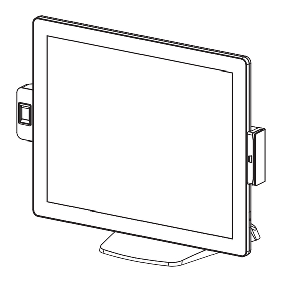
System View 2-1. Front & Side View Description Fingerprint (option) Touch screen MSR (option) Power button Stand 2-2. Rear View Description VESA top cove Cable cover Stand cover... -
Page 12: Io Ports View
2-3. IO Ports View Description Display port (option) Auto adjust Power button USB in DC in 12V USB 2.0 x2 (one is option) COM (option) Line-out (option) 2-4. Dimensions 437.44mm 391.59 mm 205.85 mm... -
Page 13: System Assembly & Disassembly
System Assembly & Disassembly Disassemble the Stand 3-1. 1. Loosen the thumb screw (x1) and slide the stand towards the IO panel to release it from the system. 2. Reverse the steps above to attach stand to the system. 3-2. Remove the Cable Cover 1. -
Page 14: Install The Power Adapter
Install the Power Adapter 3-3. The system is equipped with a 36W power adapter. Please follow the steps to install the power adapter. 2. Connect the power adapter to the 19V DC in port and then route the cable through the hole of the stand as shown in the picture. 3. -
Page 15: Peripheral Installation
Peripheral Installation Install the MSR Module 4-1. 2. Insert the MSR module in place and fasten the screws (x2) on the back to secure the module. -
Page 16: Install The Fingerprint Module
Install the Fingerprint Module 4-2. 2. Insert the Fingerprint module in place and fasten the screws (x2) on the back to secure the module. -
Page 17: Install The Ibutton Module
Install the iButton Module 4-3. 2. Insert the iButton module in place and fasten the screws (x2) on the back to secure the module. -
Page 18: Install The Lcm Module
Install the LCM Module 4-4. 1. Follow the steps in Chapter 3-1 to diassemble the stand from the LCD panel. 2. Remove the thumb screw (x1) from the VESA top cover and then pull the cover 3. Attach the VFD module to system by fastening the thumb screw (x1). 4. - Page 19 Model Name Pulse Ultra Touch Monitor 17 Mainboard LCD Touch Panel LCD size 17” TFT LED Panel Brightness (cd/m²) 350 nits Maximan resolution 1280 x 1024 Touch screen type Tilt angle 0~90 I/O Ports USB in 1 x USB 2.0 (Type B to PC) USB out 1 x USB 2.0 (Type A to device)
-
Page 20: D01 Ad Board Layout
6-1. D01 AD Board Layout... -
Page 21: Connectors & Functions
6-2. Connectors & Functions Connector Function CN1/3/4 USB connector (downwtream) eDP output connector Keypad connector Debug Power On/Off connector OSD On/Off LED MCU debug DVI/DP input connector CN10 USB connector upstream) CN11 Internal VGA input connector CN12 Power On/Off connector CN13 Auto adjust CN14... -
Page 22: Jumper Setting
6-3. Jumper Setting LCD ID Setting LVDS Output Panel# Resolution Interface Bits Channel LVDS 1280 x 1024 Dual Panel Jumper open Jumper short...
Need help?
Do you have a question about the Pulse Ultra Touch Monitor 17 and is the answer not in the manual?
Questions and answers