Table of Contents
Advertisement
Advertisement
Table of Contents

Related Manuals for Pall PCM500 Series

Summary of Contents for Pall PCM500 Series
- Page 1 OPERATING INSTRUCTIONS ® Pall PCM500 Series Portable Fluid Cleanliness Monitor...
-
Page 2: Preface
The PCM500 user manual is provided to assist users in maximising the benefits of the PCM500 portable fluid cleanliness monitor. As part of the continuous improvement process that Pall adopt in the development of technology and satisfying customer requirements, this information or procedure may be subject to change. - Page 3 Section 10 Spare parts list Section 11 Covers the disposal of equipment Appendix A Details the Pall PCM500 series worldwide aftermarket and calibration service. Appendix B Details the Mesh Screen Manifold exchange procedure MANUAL PART NUMBER ISSUE DATE MA-PCM500...
-
Page 5: Warnings, Cautions And Notes
WARNINGS, CAUTIONS AND NOTES Care must be taken in referring to this manual so as to ensure adherence with all warnings, cautions and important notes. These carry information related to the safety of personnel and the integrity and satisfactory operation of plant. WARNINGS: THESE ARE INSTRUCTIONS THAT DRAW ATTENTION TO THE RISK OF INJURY OR DEATH. -
Page 6: Table Of Contents
Section 5: PCM500/PCM500W Connecting the Monitor Appendix B: PCM500/PCM500W Mesh 5.1 Connection Options Manifold Exchange procedure 5.2 Connections 5.2.1 High Pressure Line Pall World wide warranty 5.2.2 Low Pressure Line 5.2.3 Reservoir Sampling 5.2.4 Bottle Sampling 5.3 Operational Checks 5.4 Installation Checks... -
Page 7: Specification And Requirements
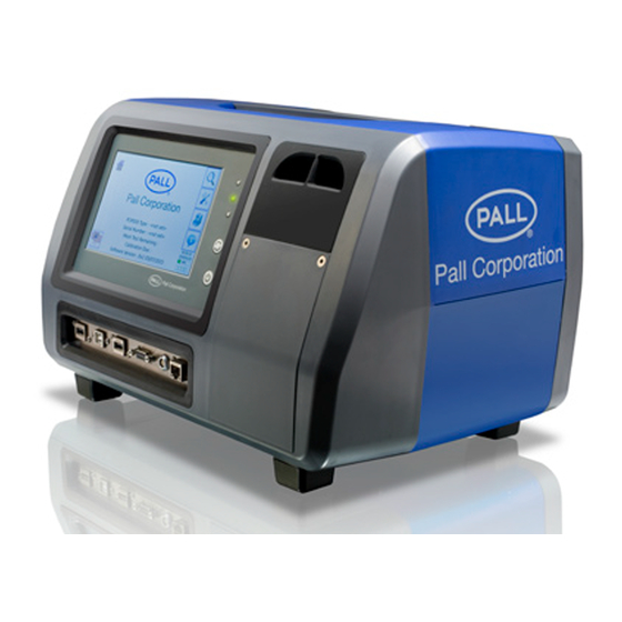
Cleanliness Monitors Specification and Requirements General Description The Pall PCM500/PCM500W is specifically developed as a portable diagnostic monitoring device that provides an assessment of system fluid cleanliness. A fixed display/controller allows for simple menu driven input of sample identification, monitor configuration and data output in ISO4406, SAE AS 4059 Table 1 (NAS 1638) or SAE AS 4059 Table 2 formats. -
Page 8: Ambient Environment
Dust and water protection IP65 (NEMA 4) Relative Humidity 95%rh non-condensing Operating Altitude <2000 metres WARNING: Do not use the PCM500 Series Monitor in an explosive atmosphere 1.4 Electrical External Mains Power Supply Unit Input 100 – 240 VAC (Auto Ranging) (PSU) Accessory Frequency 50 –... -
Page 9: Product Specification
Section 1: Pall PCM500 and PCM500W Fluid Cleanliness Monitors Specification and Requirements Product Specification Weight 11 Kg (24 lb) Dimensions 400 x 260 x 250 mm (15.75” x 10.2” x 10“) Monitoring range ISO4406 11/9/7 to 23/21/17 Monitoring range SAE AS4059F Table 1... -
Page 10: And Packaging
If any connect the PCM500 on-line or sample fluid items are missing, contact Pall or an directly from a system reservoir without approved agent. breaking lines thereby avoiding extraneous contamination. -
Page 11: General Principles
Section 4: Pall PCM500 and PCM500W BUTTONS: • START/STOP/REPEAT (test) Series Fluid Cleanliness Monitor • ON /OFF Principles of Operation The test Start/Stop button is active on release. The ON button is active on 4.1 General Principles release but OFF requires pressing for 2 - Upon starting a test sequence the PCM500 3 seconds to shut down. -
Page 12: Communication Panel
4.4 Communications Panel USB-A Socket 1 Text file upload/download from memory device USB-B Socket PC connection for setup/control of PCM500 USB-A Socket 2 Printer connection DB9 Female RS232 / PLC control (See section 7) 2-Pin Socket Voltage free contact. Relay RJ45 Cat5 Ethernet 10/100 base Screen indication of valid port connection... -
Page 13: Battery
WARNING: Use only battery packs supplied by the 4. The battery connector is removed by manufacturer or Pall agent. pulling straight on the outer body. Do not Serious damage will occur if a rotate the connector, otherwise damage battery of different chemistry or specification is used. -
Page 14: Connection Options
Caution: In the interests of Section 5: Connecting the PCM500 safety, always remove the end cap from the return line 5.1 Connection Options before connecting the inlet hose to high-pressure. If the A general checklist for the user before PCM Pressure Reduction Valve does not starting is given in section 5.3 and also in the regulate properly then excess outlet pressure ‘Useful information’... -
Page 15: Connections
Connection Options 5.2.1 High Pressure Line (>1 to 315 bar) 5.2.2 Low Pressure Line (0 - 1 bar) <1 bar at test point: - remove HP connector and couple hose direct. -
Page 16: Reservoir Sampling
5.2 Connection Options 5.2.3 Reservoir Sampling (0 bar: - Direct coupled hose or use sampling stalk. Remove high-pressure connector Note: Ensure sample point and hose connection are cleaned before mating 5.2.4 Bottle Sampling (0 - 1 bar) When bottle sampling it is important to prevent When sampling from a bottle or container, it is extraneous contaminant entering the sample, advised to run a single test to waste with a... -
Page 17: Operational Checks
5) Connect the black hose to the with Pall logo. The next phase of start-up is appropriate sampling point. Check for test firing of the internal valves (six clicks). -
Page 18: Screen Button Description
6.3 Button Descriptions Main Menu File Info Language Home Set-up Tools Navigation Cancel Down Previous Confirm Undo Forward Back Editing & Data Edit Delete Create Open Warnings Contact Critical Warning Shutdown Tools and Functions Set Label Format Clock Print Date Communi- Temp. -
Page 19: The Screens Flow Chart
6.4 Display Flow Chart The display flow chart can be used to help the new user become familiar with the PCM500 display operating sequence. The flow chart consists of a number of views using the previous Icon listing to indicate their access within the screens. START Language MAIN MENU... -
Page 20: Example Screen
MESH TEST REMAINING: 1234 CALIBRATION DUE: 2016/10/24 PALL CORPORATION WWW.PALL.COM CUSTOMER OR UNIT IDENTITY HERE Support / Contact Pall 6.6 Start-up Sequence Press and release the power on/off button Contact screen for technical support on the front panel. This will power-up the... -
Page 21: Sampling
6.7 Sampling Main Menu Screen Sample can be on-line, from a reservoir, or bottled oil sources. Refer to sections 1 ‘Specifications and section 5.1 ‘Connection Options’. PCM500W – SERIAL No. 2345 MESH TEST REMAINING: 1234 On Line or Tank Sampling Routine CALIBRATION DUE: 2016/10/24 CUSTOMER OR UNIT IDENTITY HERE From the main menu... - Page 22 Warm Up Screen example. A single test result screen If the sample fluid temperature is below the RESULT value set in Test Point, the PCM will enter a TEST NAME: NEW OIL TEST POINT: LUBE RESERVOIR warm-up cycle which pumps fluid FLUID: 32 GRADE continuously until the temperature measured...
-
Page 23: Test Point And Fluid Setup
Print results screen New Test point set-up This follows the same control method as NEW TEST POINT USB transfer but there is an option to print one or all results if multiple tests are TEST POINT NAME = RESERVOIR available. If one is selected then it will be that NUMBER OF TESTS = 3 currently open on the result screen. - Page 24 Edit button. If PPM is selected then four absolute water constants appear for editing. C1, C2, C3 and C4 are updated using values supplied by Pall Corporation, Load a stored Test Point contact Pall for availability. From the OPEN button in Test point, select a •...
-
Page 25: Code Alarm Setup
AS4059 Table 1 FLUIDS FLUID A FLUID B FLUID C FLUID D FLUID E FLUID F 6.9 Code Alarm Setup Each Test Point is allocated an alarm point AS4059 Table 2 setup for the three coding standards and whether a two or three-part code is selected. The default alarms are set to maximum code numbers and the user can adjust the code alarms to their required limits. - Page 26 Opening an individual Test Point lists all tests under that TEST POINTS name. Single or All Test TEST POINT A Labels can be loaded to USB Flash Drive or TEST POINT B printed TEST POINT C TEST POINT D TEST POINT E TEST POINT B LABELS TEST POINT F RESERVOIR FILTER-IN...
-
Page 27: Tools Screens
Deleting DELETE SELECTION? Throughout the data management screens there are several that include the delete DELETE FLUID OR TEST OR NAME OR POINT option. This includes Points; Names; Tests and Fluids. To enable this action a password must be entered. The default password issued is DEL1 but this can be changed by the user in the TOOLS screen. - Page 28 Temperature Temperature reporting is changed by simply Code Format pressing the button to switch between There are several options for Code format Fahrenheit and Celsius within the three standards provided. • ISO 4406 -/6µ/14µ (2-part) • ISO 4406 4µ/6µ/14µ (3-part) •...
- Page 29 Printer Test To test a Bluetooth or USB connection between PCM500 and Printer press the Printer button. A progress screen will open to show the two connection options. Press the option required and a corresponding progress bar indicates the communication attempt between PCM and Printer.
- Page 30 Section 7: Pall PCM500 Series Fluid C – PCM500 status: 0: The unit is in standby. Cleanliness Monitors 1: The unit has ended a test and it is waiting to start a new test at the set time Interface Protocol for PLC control using interval.
- Page 31 PCM500 Error codes The PCM500 is currently running a test: the command is ignored. The codes are in hexadecimal format. The PCM500 is in standby: the test series is initiated, with the maximum number of Byte Code Description tests as previously entered from the display. The PCM500 is waiting between tests: a 0x01 Very low battery...
- Page 32 3. Modes of Operation a). – Test timing set on the PCM500 In the PCM500 Test Point setup, enter the number of tests to be performed in a test- cycle and also include any delay between individual tests. A test sequence can then be started from the PCM500 or from the PLC.
-
Page 33: Change Procedure
Glycol (MEG). ❶ ❶ When using PCM500W, stabilization ❶ ❶ Contact Pall if there is doubt over the times can affect the water sensor accuracy compatibility of test sample and Rust Veto when sampling fluids of vastly differing water transit fluid. - Page 34 Section 9: Pall PCM500 and PCM500W Fluid Cleanliness Monitors Function Codes, Possible Cause(s) and Corrective Actions Function codes either are flags only to indicate to the user an awareness of a borderline test situation or curtail the test. An alarm will indicate registered function codes that can be cancelled by pressing any key.
- Page 35 Section 9: Pall PCM500 and PCM500W Fluid Cleanliness Monitors (continued Function Codes, Possible Cause(s) and Corrective Actions Function PCM500 PCM500 Status Possible Cause Corrective Action Code Condition Unit completes test. Water in Oil Warning displayed on Information only. Outside set limit screen.
- Page 36 Section 9: Pall PCM500 and PCM500W Fluid Cleanliness Monitors (continued) Function Codes, Possible Cause(s) and Corrective Actions Function PCM500 PCM500 Status Possible Cause Corrective Action Code Condition Internal Error/warning message on peripheral screen (if possible). Alarm No communication Contact Pall or an micro- set.
- Page 37 Section 9: Pall PCM500 and PCM500W Fluid Cleanliness Monitors (continued) Function Codes, Possible Cause(s) and Corrective Actions Function PCM500 PCM500 Status Possible Cause Corrective Action Code Condition Solid Pre-set Solid Display warning message on Repeat test to verify. Contaminatio contamination level screen.
-
Page 38: Parts List
Section 10: Pall PCM500 and PCM500W Fluid Cleanliness Monitors Spare Parts List Part Number Description PCM500.211 Power Supply Unit PCM200.235A Mains Cable UK PCM200.235B Mains Cable Europe PCM200.235C Mains Cable USA PCM200.235D Mains Cable Australasia PCM200.235E Mains Cable Japan PCM500.213ASS Battery Pack PCM200.239... -
Page 39: Equipment
Pall distributor or the manufacturer for advice obtained and read to ensure that on a replacement part. Replacement is contaminated component parts are disposed carried out by a Pall service centre, where a of safely. new hose installation is validated for maximum operating pressure prior to release. -
Page 40: Appendix A: Calibration And Aftermarket
Calibration and Aftermarket Service • Software update to latest release level • Check for oil leaks and rectification as necessary Pall PCM500 series fluid cleanliness • Check condition of Last chance filter monitors are designed to provide trouble free • Low-pressure hose replacement operation for many years. -
Page 41: Manifold Exchange Procedure
Appendix B: PCM500.500 Mesh 1. Use an M5 socket driver to remove four M5 Flange securing nuts. Manifold Exchange Procedure 2. Carefully remove the mesh manifold by pulling on the outer body and place in This procedure must be carried out in a clean protective packaging that came with the environment and great care taken to avoid replacement mesh manifold. - Page 42 Appendix D: PCM500.500 Mesh Manifold Exchange Procedure Replacement Mesh Manifold – ‘O’-ring fitting 5. Slide the Mesh Manifold onto the four bolts and push firmly onto the O-rings. 6. Fit the four M5 Flange nuts. Be very careful not to cross thread onto the bolts. 7.
-
Page 43: Pall World Wide Warranty
Cleanliness Monitors World-wide Warranty Pall products are rigidly inspected during manufacture and on completion by a modern Quality Control Department and are guaranteed for a period of one year from date of commissioning, against defective materials and workmanship when properly installed and operated at design conditions.
Need help?
Do you have a question about the PCM500 Series and is the answer not in the manual?
Questions and answers
Добрый день! Прошу Вас уточнить занесен ли в Госреестр данное оборудование? Заранее благодарю за обратную связь!