Table of Contents
Advertisement
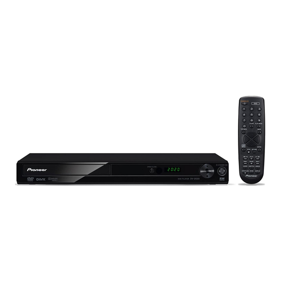
DVD PLAYER
DV-2022
DV-2020
THIS MANUAL IS APPLICABLE TO THE FOLLOWING MODEL(S) AND TYPE(S).
Model
Type
DV-2022
YXZT5
DV-2020
YXZT5
PIONEER CORPORATION
PIONEER ELECTRONICS (USA) INC. P.O. Box 1760, Long Beach, CA 90801-1760, U.S.A.
PIONEER EUROPE NV Haven 1087, Keetberglaan 1, 9120 Melsele, Belgium
PIONEER ELECTRONICS ASIACENTRE PTE. LTD. 253 Alexandra Road, #04-01, Singapore 159936
PIONEER CORPORATION
Power Requirement
AC 220 V to 240 V
AC 220 V to 240 V
1-1, Shin-ogura, Saiwai-ku, Kawasaki-shi, Kanagawa 212-0031, Japan
2011
DV-2022
Region No.
Serial No.
2
&&&&######YY
2
&&&&######YY
K-ZZZ JULY
ORDER NO.
RRV4202
Remarks
YY: Europe
YY: Europe
2011 Printed in Japan
Advertisement
Table of Contents

Related Manuals for Pioneer DV-2022


Summary of Contents for Pioneer DV-2022
- Page 1 PIONEER CORPORATION 1-1, Shin-ogura, Saiwai-ku, Kawasaki-shi, Kanagawa 212-0031, Japan PIONEER ELECTRONICS (USA) INC. P.O. Box 1760, Long Beach, CA 90801-1760, U.S.A. PIONEER EUROPE NV Haven 1087, Keetberglaan 1, 9120 Melsele, Belgium PIONEER ELECTRONICS ASIACENTRE PTE. LTD. 253 Alexandra Road, #04-01, Singapore 159936...
-
Page 2: Safety Information
LD ON mode in the test mode oscillates with the laser forcibly. 2. When the cover is open, close viewing through the objective lens with the naked eye will cause exposure to the laser beam. ∗ : See page 23. DV-2022... -
Page 3: Table Of Contents
10.10 WAVEFORMS................................58 11. PCB CONNECTION DIAGRAM ............................60 11.1 DVD MT PCB ASSY ..............................60 11.2 OPERATION PCB, POWER PCB and LOADING MOTOR PCB ASSY ..............62 11.3 REAR JACK PCB ASSY ............................. 64 12. PCB PARTS LIST................................65 DV-2022... -
Page 4: Service Precautions
Flux smoke away from it. Pick Up PCB Note There are 4 solder pads. If the Short circuit using a top & bottom pads are shorted soldering iron. together, this solder must be removed for the DVD to operate. Fig. 1 DV-2022... - Page 5 When soldering or unsoldering, completely remove all of the solder from the pins or solder area, and be sure to heat the soldering points with the lead free solder until it melts sufficiently. Recommendations Recommended lead free solder composition is Sn-3.0Ag-0.5Cu. DV-2022...
- Page 6 2. Press and hold the 'STOP' key on the front panel. 3. Simultaneously press and hold the POWER key on the front panel. 4. The 4 digit password has now been cleared. NOTE: The above procedure will reset ALL of the player's settings to the default factory state. DV-2022...
-
Page 7: Specifications
Power consumption (standby) DV-2022/DV-2020 ......0.5 W Weight ........1.2 kg External dimensions . -
Page 8: Disc/Content Format
BD/DVD recorder, if burn quality is not recording unit, consisting of a complete set of data from good due to characteristics of the disc, scratches, dirt on lead-in to lead-out. the disc, dirt on the recorder’s lens, etc. DV-2022... - Page 9 • The filename of the movie file has to be repeated at the beginning of the filename for the external subtitle file. • The number of external subtitle files which can be switched for the same movie file is limited to a maximum of 10. DV-2022...
-
Page 10: Basic Items For Service
Before shipping out the product, be sure to clean the following positions by using the prescribed cleaning tools. Position to be cleaned Name Part No. Remarks Pickup leneses Cleaning liquid GEM1004 Refer to “9.3 DVD MECHA SECTION”. Cleaning paper GED-008 DV-2022... -
Page 11: Pcb Locations
DVD MECHA ASSY DVD MT PCB ASSY REAR JACK PCB ASSY POWER PCB ASSY OPERATION PCB ASSY LIST OF ASSEMBLIES Mark Symbol and Description DV-2022/YXZT5 DV-2020/YXZT5 1..DVD MT PCB ASSY A2P031A130 A2P006A130 1..OPERATION PCB ASSY A2P031A270 A2P006A270 1..REAR JACK PCB ASSY... -
Page 12: Block Diagram
4. BLOCK DIAGRAM 4.1 OVERALL WIRING DIAGRAM CP502 CP4003 AC220-240V(EU/RUS) CONNECTOR CD501_2 CP501 AT+12V J7302 AT+12V GND(D) GND(D) POWER PCB ASSY GND(D) GND(D) (DV-2022 :A2P024A240) AT+3.3V AT+3.3V AT+3.3V AT+3.3V (DV-2020 :A2P001A240) AT+6V AT+6V AT+6V AT+6V GND(M) GND(M) GND(M) GND(M) VBUS POWER PCB... - Page 13 SP1- SP1- SP1+ SP1+ M2601 DVD MT PCB ASSY(1/6-6/6) JQ24-35H390 (DV-2022/YXZT5 :A2P031A130) (DV-2020/YXZT5 :A2P006A130) DVD PCB PCB130 DMK137 • NOTE FOR FUSE REPLACEMENT CAUTION - FOR CONTINUED PROTECTION AGAINST RISK OF FIRE, REPLACE WITH SAME TYPE AND RATINGS OF FUSE.
-
Page 14: Overall Block Diagram
4.2 OVERALL BLOCK DIAGRAM DV-2022... -
Page 15: Dvd Loader/Mpeg Block Diagram
4.3 DVD LOADER/MPEG BLOCK DIAGRAM DV-2022... -
Page 16: Power Block Diagram
4.4 POWER BLOCK DIAGRAM DV-2022... -
Page 17: Diagnosis
OPEN/CLOSE Is the voltage at pin 8 and Check P.CON 6V line of POWER BLOCK. 19 of IC2301 about DC6V ? Is the lose connection Check CP2302 connection to DECK . at CP2302 to DECK ? Change DVD LOADER. DV-2022... - Page 18 Is there a voltage (beam current) at Q2302 Check LOADER BLOCK. and Q2303? Is there a signal at pin 100 of IC4001? Check IC4001 and peripheral circuit. Is there video signal at Check J7302 and peripheral circuit. J7302. Change IC4001. DV-2022...
- Page 19 NO ANALOG AUDIO ON PLAYBACK. Is there AUDIO signal at Check J7302and peripheral circuit. pins 1 and 7 of IC8003? Is there AUDIO signal at pins 2 and 6 of IC8003? Check at pins 114 and 116 of IC4001. Change IC8003. DV-2022...
-
Page 20: Sequence After Power On
Get Start up types AC ON Upgrade or start by user FL initialization FL initialization The opening picture appears [DVD IC] Accesses 64M SDRAM (Remaining part) Disc detection (Focus control) Spindle turn Read Disc information code Disc Identification The picture appear DV-2022... - Page 21 Any kind of symptoms (no power, a failure in any of the servo, video and audio systems, etc.) may be (DVD MT PCB Assy : IC4001) generated, because the DVD processing is performed by a single chip. 64M SDRAM No power. (DVD MT PCB Assy : IC4005) Block noise is generated during playback. DV-2022...
-
Page 22: Method For Diagnosing Degradation Of The Lds On The Pickup Assy
R4025 NR2301 D2301 R4066 D2302 C2320_1 C2321_1 C4007 C4005 R4039 C4052 R4058 R2320 C4013 for DVD laser diode C4014 R4029 R4053 R4047 C4050 R4075 R4004 Q4008 C4091 CP2302 C2306 Q4009 R2325 C4134 W808 C4100 C4065 IC2301 C4112 CP4002 R2326 DV-2022... -
Page 23: Service Mode
• After going into service mode, if you play back the disc, "DISC-NON" is displayed. • The video signal and the audio signal are outputted during the servicemode. • The SKIP key and the SCAN key are effective during the service mode. SERVICE MODE: OFF POWER GGF1381 Service remote control unit DV-2022... -
Page 24: Service Mode In
• Press the [ESC] key of the remote control unit. 3 LD ON DVD : Press the [TEST] and [1] keys in order, and turn on the laser diode (650n). : Press the [TEST] and [4] keys in order, and turn on the laser diode (780n). DV-2022... -
Page 25: Display Specification Of The Service Mode
: [NTSC] PAL system : [PAL] Automatic setting : [AUTO] Scart terminal output [SK – ∗ ∗] (Display only the WY model which can do the output setting of scart terminal.) VIDEO : [00] S-VIDEO : [01] : [02] DV-2022... -
Page 26: Functional Specification Of The Shortcut Key
Region confirmation mode (ESC + A.MON [Service remote control unit] + "1"-"8" [Service remote control unit] keys) After you press the A.MON key while holding the ESC key pressed and then input the region number, if the number is different from that set in the unit, an error message is displayed, and the tray opens. DV-2022... -
Page 27: Functional Specification Of The Service Mode
-2 : NG 7.0e -4 : NG 3 EDC/ID error history (ID Address, EDC/ID errors, last eight errors) Note: ∗ Error of AV1 is not supported in this player. Indication plan contents Character in bold : Item name : Information display DV-2022... -
Page 28: Disassembly
Pick Up Unit to keep the Flux smoke away from it. 5. When installing the DVD Deck, remove all the soldering on the short circuit position after the connection of Pick Up PCB and DVD MT PCB connector. DV-2022... - Page 29 4. Remove the Traverse Ass'y. Loader Sub Ass'y Loader Sub Ass'y Pulley Motor Loading Motor Loading Motor PCB Ass'y Insulator (R) Screw Torque: 1.0 ± 0.3kgf cm (Screw (2)) Traverse Ass' y Fig. 2-3-A Fig. 2-2-A Screw Torque: 2.0 ± 0.3kgf cm DV-2022...
- Page 30 2-5: CLAMPER ASS'Y (Refer to Fig. 2-5-A) the direction, it cannot Ass'y (1) 1. Unlock the Spring Clamper. 2. Remove the Clamper Check Hook Spring Clamper Check Position Clamper Check Position Frame Sub Ass'y Check Hook UnLock Loading Motor PCB Ass'y Fig. 2-3-E Fig. 2-5-A DV-2022...
- Page 31 To Pick Up PCB Rack Feed Ass'y Gear Middle Reinforcement Plate Screw Torque: 1.3 0.3kgf cm (Screw (2)) Scre w Torque: 2.5 0.3kgf cm (Screw (1)) Scre w Torque: 1.0 0.3kgf cm (Screw (3)) Fig. 2-7-A Printing Surface Fold Fig. 2-8 DV-2022...
-
Page 32: Each Setting And Adjustment
While the screen shown at left is being displayed, updating is in progress. DO NOT TURN OFF THE POWER DURING UPDATING. 4 Updating of the firmware is completed. When the screen with the Pioneer logo is displayed, updating is completed. The time required for updating is about 2 minutes. DV-2022... - Page 33 2 If updating of the firmware using the disc for updating failed • Was the disc for updating recognized properly? Check if the volume label of the disc is PIONEER. • Is playback of a disc other than the disc for updating possible? If playback of a test CD is also impossible, a reading section, such as PU, may be defective.
-
Page 34: Exploded Views And Parts List
Screws adjacent to b mark on product are used for disassembly. For the applying amount of lubricants or glue, follow the instructions in this manual. (In the case of no amount instructions, apply as you think it appropriate.) 9.1 PACKING SECTION DV-2022... - Page 35 See Contrast table (2) 4 Package Pad 792WHAA457 5 Gift Box See Contrast table (2) (2) CONTRAST TABLE DV-2022/YXZT5 and DV-2020/YXZT5 are constructed the same except for the following: Mark No. Symbol and Description DV-2022/YXZT5 DV-2020/YXZT5 3 Remote Control Unit 076E0SH051...
-
Page 36: Exterior Section
9.2 EXTERIOR SECTION Refer to "9.3 DVD MECHA SECTION". DV-2022... - Page 37 14 Screw, TAP TITE(B) BK (3x6) 810923060S 15 Screw, TAP TITE(P) (2.6x8) 811022680U (2) CONTRAST TABLE DV-2022/YXZT5 and DV-2020/YXZT5 are constructed the same except for the following: Mark No. Symbol and Description DV-2022/YXZT5 DV-2020/YXZT5 1 DVD MT PCB ASSY A2P031A130 A2P006A130 >...
-
Page 38: Dvd Mecha Section
If the repair is needed, replace the DVD MECHA ASS'Y. Note: NAME PART NO. MARK Applying positions AA and AB for the grease are NOTE: displayed for this section. SANKOL (CFD-5007Z) GEM1092 Check if the correct grease is applied for each FLOIL (G-313Y) GEM1062 position. DV-2022... - Page 39 21 Gear, Middle 92P100202A 22 Gear, Motor 92P100203A 23 Insulator (R) 92P200028A 24 Screw, Tap Tite(P) PanWH5.4 (1.7x8) 92P700020A 25 Screw, Tap Tite(P) Pan WH8 (2x8) 92P700021A 26 Screw, Pan (1.7x2.3) 814011723U 27 Screw, T-Tite(B) Camera Pan (1.7x5.0) 813381750U DV-2022...
-
Page 40: Schematic Diagram
USB_P_ON-L VDD33_USB USBN W808 USBP VSS_USB R4039 LEM_DIO/OPEN PAD_VRT SF_CK LEM_STB/STOP 5.1K 1/16W +-1% LEM_SCL/P.SW UP1_6/SCL VDD12_USB UP1_7/SDA SF_CS V+1R2 SF_DO SF_DI USB_GND 35 36 37 38 40 41 45 46 47 48 49 50 51 52 53 V+3V DV-2022... - Page 41 DBA0 C4073 DVDD33 0.1 B DRAS# RAS# DCAS# PEG/MICON IC CAS# IC4001 T1389DE/J-L DVSS12 DVD MT PCB ASSY(1/6) DWE# RWE# (DV-2022/YXZT5 :A2P031A130) (DV-2020/YXZT5 :A2P006A130) MA11 RA11 R4066 SDCLK SDCLK 33 1/16W DVDD33 C4071 DQM1 DQM1 RD14 64 RD13 DQ10 RD10...
-
Page 42: Dvd Mt Pcb Assy (2/6)
C4055 FROM POWER PORT 0.1 B AT+3.3V D_GND TP4001 NOTE:THIS SCHEMATIC DIAGRAM IS THE LATEST AT THE TIME NOTE:THE DC VOLTAGE EACH PART WAS OF PRINTING AND SUBJECT TO CHANGE WITHOUT NOTICE MEASURED WITH THE DIGITAL TESTER DURING PLAYBACK. DV-2022... - Page 43 MEMORY/USB SCHEMATIC DIAGRAM (DVD MT PCB) DVD MT PCB ASSY(2/6) 16M SERIAL FLASH IC (DV-2022/YXZT5 :A2P031A130) IC4004 GD25Q16SCPR C4062 (DV-2020/YXZT5 :A2P006A130) SFLASH_CS 0.1 B R4043 R4047 33 1/16W 10K 1/16W SFLASH_CK TP4004 SFLASH_DI V+3V DV-2022 Only V+5V_USB USB_P_ON-H USB_P_ON-L USB_P_ON-H...
-
Page 44: Dvd Mt Pcb Assy (3/6)
MOT_SPDL- C2311 CAUTION ATTENTION :SINCE THESE PARTS MARKED BY :LES PIECES REPAREES PAR UN ETANT CRITICAL FOR SAFETY,USE ONES DANGEREUSES AN POINT DE VUE SECURITE DESCRIBED IN PARTS LIST ONLY N’UTILISER QUE CELLS DECRITES DANS LA NOMENCLATURE DES PIECES DV-2022... - Page 45 OPIN VOTR- Vcc2 VOTR+ VOLD- VOSL+ DVD MT PCB ASSY(3/6) VOLD+ VOSL- (DV-2022/YXZT5 :A2P031A130) VOTK- VOFC- (DV-2020/YXZT5 :A2P006A130) VOTK+ VOFC+ NOTE:THE DC VOLTAGE EACH PART WAS NOTE:THIS SCHEMATIC DIAGRAM IS THE LATEST AT THE TIME MEASURED WITH THE DIGITAL TESTER...
-
Page 46: Dvd Mt Pcb Assy (4/6)
560P CH ASPDIF R8060 120K 1/16W R8059 8.2K 1/16W +-1% AUDIO_R AUDIO_L R8049 8.2K 1/16W +-1% R8048 JACK MUTE(H:ON) Q8014 120K 1/16W KTA1504S_Y_RTK XAMUTE(L:ON) Q8013 RT1N241C NOTE:THE DC VOLTAGE EACH PART WAS MEASURED WITH THE DIGITAL TESTER DURING PLAYBACK. DV-2022... - Page 47 AUDIO JACK SCHEMATIC DIAGRAM (DVD MT PCB) DVD MT PCB ASSY(4/6) (DV-2022/YXZT5 :A2P031A130) (DV-2020/YXZT5 :A2P006A130) R8060 R8067 120K 1/16W 24K 1/16W +-1% C8073 R8059 R8066 C8069 R8080 8.2K 1/16W +-1% 10K 1/16W 68P CH 470 1/16W (1608) MUTE SW R8081 Q8018 -1.2...
-
Page 48: Dvd Mt Pcb Assy (5/6)
10.5 DVD MT PCB ASSY (5/6) DVD MT PCB ASSY(5/6) (DV-2022/YXZT5 :A2P031A130) (DV-2020/YXZT5 :A2P006A130) TO AUDIO JACK V+12 AUDIO_R AUDIO_L C7303 FROM/TO MPEG/MICON/DSP R/CR VIDEO_DRIVER IC B/CB IC7301 NJW1351RB1(TE1) CVBS TXD/VSEL 1.95 3.44 RXD/SQ 3.24 3.09 C7302 W864 CVBS 0.55... - Page 49 CVBS AUDIO L V+12 AUDIO R R7303 CVBS_OUT 1/16W +-1% G/Y_OUT B/U_OUT R/V_OUT AUDIO OUT CVBS J7302_1 J8002 RCA-117-02 RCA-232-00-01 NOTE:THIS SCHEMATIC DIAGRAM IS THE LATEST AT THE TIME OF PRINTING AND SUBJECT TO CHANGE WITHOUT NOTICE PCB130 DMK137 DV-2022...
-
Page 50: Dvd Mt Pcb Assy (6/6)
GND(M) GND(M) ATTENTION CAUTION :LES PIECES REPAREES PAR UN ETANT :SINCE THESE PARTS MARKED BY DANGEREUSES AN POINT DE VUE SECURITE CRITICAL FOR SAFETY,USE ONES N’UTILISER QUE CELLS DECRITES DESCRIBED IN PARTS LIST ONLY DANS LA NOMENCLATURE DES PIECES DV-2022... - Page 51 DVD MT PCB ASSY(6/6) (DV-2022/YXZT5 :A2P031A130) (DV-2020/YXZT5 :A2P006A130) TO AUDIO B4002 (AUDIO AMP) V+12 (VIDEO/OPT/COAX) FCM1608KF-102T02 V+5V V+5V D_GND TO LOADER/MOTOR DRV B4001 V+5S (OPU) V+5S FCM1608KF-102T02 (F/E) W806 (MOTOR) V+5R5 V+5R5 M_GND C4116 D_GND 0.001 B ADACVDD REG Q4001...
-
Page 52: Operation Pcb Assy
10.7 OPERATION PCB ASSY FROM/TO DVD PCB DV-2022 Only USB CONNECTOR CP6602 V651 CP6601 (CP4004) C-001-1-4K221400 A2001WR-5A DIG1 VBUS PGND USB_DN USBP USB_DP USBN GND(SHIELD) CORD CONNECTOR CD6601 3.7 3.2 3.5 3.2 2 EH251502 C659 Vout R666 EV+3OR5 47 1/16W... - Page 53 DISPLAY SCHEMATIC DIAGRAM (OPERATION PCB) OPERATION PCB ASSY V651 DL-E50221AG1 DIG1 DIG2 DIG3 DIG4 DIG5 (DV-2022/YXZT5 :A2P031A270) (DV-2020/YXZT5 :A2P006A270) 3.7 3.2 3.5 3.2 2.75 3.7 3.5 3.62 3.5 3.5 3.5 3.5 3.7 2.75 CD601 (CP4002) FFC1009130050250700T8-F00 LEM_CLK/P.SW LEM_CLK/P.SW LEM_DIO/OPEN LEM_DIO/OPEN 3.62...
-
Page 54: Rear Jack Pcb Assy
820 1/16W R8101 4.7K 1/16W PROTECT Q8104 2N7002K-RTK/P A_GND NOTE:THE DC VOLTAGE EACH PART WAS NOTE:THIS SCHEMATIC DIAGRAM IS THE LATEST AT THE TIME MEASURED WITH THE DIGITAL TESTER OF PRINTING AND SUBJECT TO CHANGE WITHOUT NOTICE DURING PLAYBACK. DV-2022... - Page 55 21PIN SCHEMATIC DIAGRAM (SCART PCB) REAR JACK PCB ASSY (YXZT5 :A2P006A250) 21PIN CONNECTOR J8101 RGB-05D R8114 21PIN_R 1/16W R8115 21PIN_L 220 1/16W L8101 21PIN_CTL 10uH 0405 G/Y_VIDEO_OUT B/U_VIDEO_OUT R/V_VIDEO_OUT BLANKING_OUT R8119 CVBS_VIDEO_OUT 1/16W R8109 1/10W PCB250 DEK232 DV-2022...
-
Page 56: Power Pcb Assy
CP501 A3963WR03P2 CD501_2 MO27-004BK T501 81140064 1.6A(T) 250V F501 392_1160_0440 17.62 12.66 1.6A 250V 79.23 POWER CTL IC IC501 DV-2022 : TNY177PN DV-2020 : TNY176PN ACCESSORY 120.22 TRANSMITTER TM601 076E0SH051 R531 6.14 22K 1/16W UM-4 0.88 BT601 R03_(AB)_2P_TG_AO_DB PHOTO COUPLER IC... - Page 57 POWER SCHEMATIC DIAGRAM W807 (POWER PCB) W809 POWER PCB ASSY (DV-2022 :A2P024A240) (DV-2020 :A2P001A240) C518 W811 220P D512 1H3-A2 T501 81140064 FROM/TO POWER PORT 7.39 CD502 (CP4003) FFC12510080060251000T8-G0 L505 3.74 D527 SMAB34 10uH TSL0808 AT+12V GND(D) C506 C514 R508 R528 1.88...
-
Page 58: Waveforms
VIDEO JACK 500 s 10 s 200mV 200mV 1.0V 200ns 1.0V AUDIO JACK 500 s 1.0V 500 s 1.0V 200ns 500mV NOTE : The following waveforms were measured at the point of the corresponding balloon number in the schematic diagram. DV-2022... - Page 59 DV-2022...
-
Page 60: Pcb Connection Diagram
Connector Capacitor 1. The parts mounted on this PCB include all necessary parts for several destinations. SIDE A For further information for respective desti- nations, be sure to check with the sche- matic diagram. SIDE B P.C.Board Chip Part DV-2022... - Page 61 SIDE B SIDE B DVD MT PCB ASSY DV-2022...
-
Page 62: Operation Pcb, Power Pcb And Loading Motor Pcb Assy
C674 SW666 C653 W017 A30C5 DEK229A DEK229A W814 POWER PCB ASSY D503 D505 D502 R515 D504 C525 IC501 W001 CP501 F501 D507 C513 D508 T501 A30C5 IC502 D512 W807 DPK029A C518 W809 W004 L503 L505 D510 LOARDING MOTORPCB ASSY DV-2022... - Page 63 SIDE B SIDE B OPERATION PCB ASSY PAL/NTSC R655 R656 R658 R666 IC601 DEK229A CD601 POWER PCB ASSY LOARDING MOTORPCB ASSY BLACK YELLOW SW01 GREEN BROWN FEJ005A CD2301 WHITE DV-2022...
-
Page 64: Rear Jack Pcb Assy
11.3 REAR JACK PCB ASSY SIDE A SIDE A REAR JACK PCB ASSY A30C5 NTSC/PAL W001 CP8103 DEK232A J8101 SIDE B SIDE B REAR JACK PCB ASSY DEK232A NTSC/PAL R8102 Q8102 D8104 Q8104 R8127 Q8105 R8114 R8115 R8103 R8118 DV-2022... -
Page 65: Pcb Parts List
I1UFV5888S IC 4001 MT1389DE/J-L IC8K0389JD IC 4004 GD25Q16SCPR S2P001AF01 IC 4005 EM638165TS-6G(70NM) IG2J08165G IC 4006 RP131K121D5-TR I1ZF91K120 IC 4009 RP131K501D-TR (DV-2022) I1ZF9K5010 IC 4010 RP130N501D I1ZF9N5010 IC 7301 NJW1351RB1 (YXZT5 type) I5AF013510 IC 8003 AZ4558C IL4J045580 MISCELLANEOUS X 4001 CRYSTAL (27MHz)
Need help?
Do you have a question about the DV-2022 and is the answer not in the manual?
Questions and answers