Advertisement
Table of Contents
- 1 Table of Contents
- 2 Safety Warnings
- 3 Technical Specifications
- 4 Description of Instrument
- 5 Electrical Connections
- 6 Glossary
- 7 Operation
- 8 Setting the Regulation Parameters
- 9 Parameter Menu
- 10 Error Messages
- 11 Reference Standards
- 12 Dimensions and Connection Diagrams, 33X75 MM
- 13 Dimensions and Connection Diagrams, 72X72 MM
- 14 Dimensions and Connection Diagrams, 4-DIN
- Download this manual
Advertisement
Table of Contents

Subscribe to Our Youtube Channel
Related Manuals for Vemer HT NiPt Series


Summary of Contents for Vemer HT NiPt Series
- Page 1 ��������������� �������� �� ��� ������� ����� ���� ������ ������� ���� ���������� ������ �� ��� ����������������� ���������...
-
Page 3: Table Of Contents
Contents � Safety warnings Page � Technical specifications Page � Description of instrument Page � Electrical connections Page � Glossary Page � Operation Page � Setting the regulation parameters Page � Parameter menu Page � Error messages Page � Reference standards Page �... -
Page 4: Safety Warnings
SAFETY WARNINGS � During the installation and operation of the instrument, follow the instructions set out below: 1) The instrument should be installed by a skilled operator. 2) Strictly follow the connection diagrams when installing the instrument. 3) Do not power or connect the instrument if any part of it is damaged. 4) Before touching the terminals, make sure the wires to be connected to the instrument are not live. - Page 5 • Digital parameter setting: - Set point - Differential - Neutral zone - Output drive times - Digital input function and delay time - Alarm delay / buzzer enable time - Probe calibration offset - Resolution displayed - Temperature measurement unit - Measurement display filter (update speed) - Probe input type - Password...
- Page 6 Rear panel 33x75 mm Code Model Power supply (*) Power supply n° of Digital Infrared tollerance relays input receiver VM627700 HT NiPt-1P3D from 12 to 24 V AC/DC ±10 VM628500 HT NiPt-1P3A from 100 to 230 V AC ±15 from 140 to 300 V DC VM629300 HT NiPt-2P3D from 12 to 24 V AC/DC ±10 VM634300 HT NTC-1P3D...
-
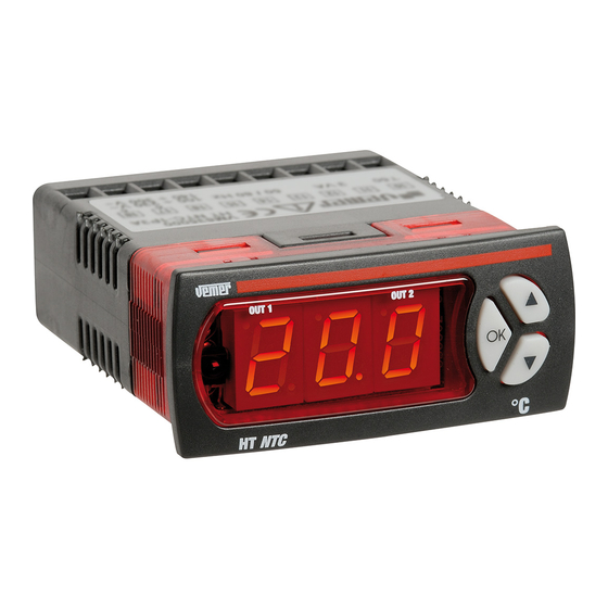
Page 7: Description Of Instrument
DESCRIPTION OF INSTRUMENT Display • A 3 digit led display with decimal point is used. For all the models, the display range is: - minimum display: -99 °C or -9.9 °C - maximum display: 999 °C or 99.9 °C Relay intervention signalling lamp: •... -
Page 8: Glossary
GLOSSARY Set point (set or operating point) • The set point is the value at which the appliance has to intervene to maintain the measurement controlled at the required level. Differential (or hysteresis) • The differential is the maximum permitted variation from the set point for the measurement controlled prior to the intervention of the appliance. - Page 9 PWM operation (in proportion to time) • This is a neutral zone type of operation in which the relays are activated periodically in impulse mode PWM Mode (the interval can be set, see the output menu). The PWM procedure modulates the power in accordance with the position occupied by the measurement within the...
- Page 10 Neutral zone operating mode [PRO=2] • In this mode, output 1 operates in reverse and output 2 in direct. The set point 1 [ST1], differential 1 [DF1] and neutral zone [DBN] values have to be set. These are parameters for both outputs. The regulator will tend to maintain the measurement controlled within the neutral zone.
- Page 11 It is therefore necessary to set both set point [ST1] and [ST2] and differential [DF1] and [DF2] values. PRO=6 mode OUT 1 OUT 1 OUT 2 Digital input open Diff. 1 Diff. 1 Set 1 Set 1 OUT 1 OUT 2 OUT 1 Digital input...
- Page 12 Reverse operating mode with set point and differential switching from digital input. [PRO=8] • In this mode, both outputs operate in reverse, with set point 1/differential 1 or set point 2/differential 2, depending on the status of the digital input. More precisely, with set point 1/differential 1 if the digital input is open and set point 2/differential 2 if closed.
-
Page 13: Operation
differential 1 [DF1] and the neutral PRO=10 mode zone [DB1] for output 1 and all the alarm menu parameters for output 2. ON alarm The maximum alarm will be activated when the value [ST1]+[HIA] is reached and will OFF alarm be deactivated at value Set 1 [ST1]+[HIA]-[DFA]. - Page 14 operation (this also happens if no key is pressed for at least 40 seconds). Press “OK” to switch between the display of the parameter label and its numerical value. To modify a parameter: - from the display of its label or value, press “OK” and hold down for at least three seconds - the display will start to flash and will show the parameter value - use the “up”...
-
Page 15: Parameter Menu
that can be modified by pressing “up” (�). To display the value of the parameter, press “OK” (press “OK” a second time to return to the display of the parameter label). - To modify the parameter value, hold down “OK” for at least 3 seconds. - The parameter value will start to flash and it will be possible to increase or decrease it with the “up”... - Page 16 Description of parameters • Inside the tables, the labels are presented in the same order as they appear in the various menus of the instrument. [REG] regulation menu Parameter Labels of values parameters that default notes Description unit can be modified min max set-point 1 degrees LO1...
- Page 17 (7) the delay time for the driving of the outputs from the instant of instrument reset (8) the period that can be set for PWM regulation. This item is displayed only if the operating mode selected is PRO=5 (see system menu). [ING] outside input menu Parameter Labels of...
- Page 18 [ALR] alarm menu Parameter Labels of values parameters that default notes Description unit can be modified min max Output status in probe alarm condition (13) Minimum alarm shift degrees 0.1 (14) Maximum alarm shift degrees 0.1 (14) Alarm differential degrees 0.1 Alarm activation delay time Buzzer enable (15)
- Page 19 (21) If the parameter is set to “yes”, a mobile average is taken of 8 measurement values (4 seconds approx.). If “no”, this average is not calculated [SNS] sensor menu Parameter Labels of values parameters that default notes Description unit can be modified min max Sensor type 0...
- Page 20 JK Thermocouples Type of sensor Display message K (*) C (*) The instrument is set to this parameter by default. (23) this parameter is visible in NTC models only (24) this parameter is visible in TC models only [SYS] system menu Parameter Labels of values...
- Page 21 8 outputs in reverse with switching between set-point 1/differential 1 and set-point 2/differential 2 from digital input 9 channel 1 in reverse with set-point 1 and differential 1 and channel 2 in direct with set-point 2 and differential 2 10 if one channel: alarm operation; if two channels: channel 1 in reverse (with set-point 1, differential 1 and neutral zone) and channel 2 in alarm operation 11 refrigeration mode...
-
Page 22: Error Messages
defined by the “dependence” parameter: the switching point is calculated by adding a percentage “IN0” (from -100% to +100%) to the set-point of the differential (32) indicates the OFF switching point of the relay with respect to the point where the ON switching took place. -
Page 23: Reference Standards
REFERENCE STANDARDS For safety: EN 60730-2-9 For electromagnetic compatibility: EN 55014-1 EN 55014-2 EN 61000-6-2 EN 61000-6-3 - 49 - User Manual Digital Heat Regulators... -
Page 24: Dimensions And Connection Diagrams, 33X75 Mm
33x75 mm REAR PANEL DIMENSIONS HT NiPt-1P3D 65,5 HT NTC-1P3D HT JK-1P3D HT NiPt-1P3A HT NTC-1P3A HT JK-1P3A HT NiPt-2P3D HT NTC-2P3D HT JK-2P3D 33x75 mm REAR PANEL DIAGRAMS Model Connection diagram Probe Probe input input Digital Digital 3 wires input 2 wires input... - Page 25 33x75 mm REAR PANEL DIAGRAMS Model Connection diagram HT NiPt-1P3A Relay output 8(1) A/250 V~ Probe Digital Probe Digital input input input input 3 wires 2 wires Relay output 2 Relay output 2 8(1) A/250 V~ 8(1) A/250 V~ HT NiPt-2P3D Relay output 1 8(1) A/250 V~ Probe...
- Page 26 33x75 mm REAR PANEL DIAGRAMS Model Connection diagram Relay output 2 8(1) A/250 V~ HT NTC-2P3D NTC1 Relay output 1 8(1) A/250 V~ NTC2 Probe input Digital input HT JK-1P3A Relay output 8(1) A/250 V~ Probe Digital input input Probe input Digital input...
-
Page 27: Dimensions And Connection Diagrams, 72X72 Mm
72x72 mm REAR PANEL DIMENSIONS HT NiPt-.. P7A HT NTC-..P7A HT JK-..P7A 72x72 mm REAR PANEL DIAGRAMS Model Connection diagram HT NiPt-1P7A Relay output 8(1) A/250 V~ Probe input PTC Probe input PTC 3 wires 2 wires HT NiPt-2P7A Relay output 1 Relay output 2 8(1) A/250 V~ 8(1) A/250 V~... - Page 28 72x72 mm REAR PANEL DIAGRAMS Model Connection diagram HT NTC-1P7A NTC1 Relay output 8(1) A/250 V~ NTC2 Probe input HT NTC-2P7A NTC1 Relay output 1 Relay output 2 8(1) A/250 V~ 8(1) A/250 V~ NTC2 Probe input HT JK-1P7A Relay output 8(1) A/250 V~ Probe input TC HT JK-2P7A...
-
Page 29: Dimensions And Connection Diagrams, 4-Din
4 DIN DIMENSIONS MODULARS HT NiPt-..DA HT NTC-..DA HT JK-..DA 10 11 12 13 14 15 16 17 18 4 DIN DIAGRAMS MODULARS Model Connection diagram Relay output 8(1) A/250 V~ HT NiPt-1DA Digital input Probe input Probe input PTC 3 wires PTC 2 wires Relay output 2 Relay output 1... - Page 30 4 DIN DIAGRAMS MODULARS Model Connection diagram Relay output 8(1) A/250 V~ HT NTC-1DA NTC1 NTC2 Digital input Probe input Relay output 2 Relay output 1 8(1) A/250 V~ 8(1) A/250 V~ HT NTC-2DA NTC1 NTC2 Digital input Probe input Relay output 8(1) A/250 V~ HT JK-1DA...
- Page 32 I - 32032 Feltre (BL) Sede Commerciale di Brugherio Via Camp Lonc, 16 I - 20047 Brugherio (Mi) Tel +39 0439 80638 Via Belvedere 11 Fax +39 0439 80619 Phone +39/039/20901 Fax +39/039/2090222 e-mail: info@vemer.it - web site: www.vemer.it www.vemersiber.it...
Need help?
Do you have a question about the HT NiPt Series and is the answer not in the manual?
Questions and answers