Table of Contents
Advertisement
Quick Links
All manuals and user guides at all-guides.com
Service Manual
Car Audio
MODEL : AKR-0108 Series
0106 Series
AKR-0106A
4-Channel high Power (40W x 4Ch)
Electronic Tuning
Electronic Volume/Bass/Treble/Balance/Fader
Control
42 Memory Capability (18FM+12MW+12LW)
Local/DX Switch
Loudness Control
Mechanical cassette Player
Detachable Face for Anti-Theft
10 CD-changer control (option)
DAEWOO ELECTRONICS CO., LTD
http://svc.dwe.co.kr
S/M No : AKR0108EF0
1010 Series
AKR-1010RC
ACR-1010RC
AKR-1010RDS
AKR-1010C
AKR-1010
Mar. 2001
Advertisement
Table of Contents

Subscribe to Our Youtube Channel
Related Manuals for Daewoo AKR-0108 Series


Summary of Contents for Daewoo AKR-0108 Series
- Page 1 All manuals and user guides at all-guides.com S/M No : AKR0108EF0 Service Manual Car Audio MODEL : AKR-0108 Series 1010 Series 0106 Series AKR-1010RC AKR-0106A ACR-1010RC AKR-1010RDS AKR-1010C AKR-1010 4-Channel high Power (40W x 4Ch) Electronic Tuning Electronic Volume/Bass/Treble/Balance/Fader Control...
-
Page 2: Table Of Contents
All manuals and user guides at all-guides.com TABLE OF CONTENTS 1. PRODUCT SPECIFICATIONS ..........1 2. LINE DRAWING ................2 3. EMERGENCY TROUBLE SHOOT ..........3 4. ADJUSTMENTS ................6 5. SCHEMATIC DIAGRAM ............10 6. PARTS LOCATION ON P.C.BOARD ........11 7. OVERALL EXPLODED VIEW & PARTS LIST .......14 8. -
Page 3: Product Specifications
All manuals and user guides at all-guides.com 1. PRODUCT SPECIFICATIONS AUDIO SECTION Maximum output power : 40watts per channel into 4 ohms. Load impedance : 4 ohms or 8 ohms Total harmonic distortion : Less than 10% at 12 watts : 100Hz( + 3dB), 10kHz(-5 + 3dB) Frequency response : 10 + 3dB at 100Hz/10kHz... -
Page 4: Line Drawing
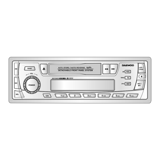
All manuals and user guides at all-guides.com 2. LINE DRAWING 2-1. FRONT SIDE AKR-1010RC - RDS Function - 4-Channel high Power (40W x 4Ch) - Electronic Tuning - Electronic Volume /Bass /Treble /Balance /Fader Control - 42 Memory Capability (18FM+12MW+12LW) - Local/DX Switch - Loudness Control - Mechanical cassette Player... -
Page 5: Emergency Trouble Shoot
All manuals and user guides at all-guides.com 3. EMERGENCY TROUBLE SHOOT 3-1. General Function Put exactly output Output connector No sound from connector in. is missing speakers Change output Output connector connector to is inferior goods superior goods Change Power IC, Power IC, Output Output Socket to Socket is inferior... - Page 6 All manuals and user guides at all-guides.com EMERGENCY TROUBLE SHOOT 3-2. Tuner Function Select exactly No selected the broadcasting Hearing noise station frequency. only Ref. CAT-7 Change tuner Tuner Module is Electrical Parts List module to inferior goods. superior goods. Weak frequency Change to goods of Extreme noise...
- Page 7 All manuals and user guides at all-guides.com EMERGENCY TROUBLE SHOOT 3-3. Tape Function Use only superior Tape is inferior No sound from goods goods speakers Put exactly deck No signal play output connector output Ref. Tape Deck Macha Change Deck Deck Mechanism Mechanism to ADC-2385...
-
Page 8: Adjustments
All manuals and user guides at all-guides.com 4. ADJUSTMENTS 4-1. TUNER MODULE ADJUSTMENT LOCATIONS CAT-7 (3 Band) CAT-6 (2 Band) - Page 9 All manuals and user guides at all-guides.com ADJUSTMENTS 4-2. MW / LW ADJUSTMENT METHOD TEST STEP ALIGNMENT TUNING ALIGNMENT INDICATOR POSITION FREQUENCY 522 KHz 522 KHz AMOSC MAXIMUM Band Covering V.T point of Range AM Board 1620 KHz 1620 KHz 7.6V Output 450 KHz...
- Page 10 All manuals and user guides at all-guides.com ADJUSTMENTS 4-3. FM ADJUSTMENT METHOD FEED SIGNAL MEASURE ADJUST STEP SUBJECT ADJUSTMENT OUTPUT POINT FROM 98.1 MHz, ANT The voltage Adjust for 0V input 60dBu, 1kHz ANT jack IF adjust FM DET (30% MOD) FM and GND 0.05V between CW03...
- Page 11 All manuals and user guides at all-guides.com ADJUSTMENTS 4-4. TAPE ADJUSTMENT METHOD NOTE : 1. Clean the playback head before adjustment 2. Prepare the test tape MTT-114 or equivalent 3. Balance, Fader, Bass & Treble ..Center position. Volume adjusted to 2Volts. TEST ADJUSTMENT STEP...
-
Page 12: Schematic Diagram
All manuals and user guides at all-guides.com for AKR-1010 & AKR-0106 Series 5. SCHEMATIC DIAGRAMS OPTION RDS Function CDC Function... -
Page 13: Parts Location On P.c.board
All manuals and user guides at all-guides.com 6. PARTS LOCATION ON P.C. BOARD 6-1. PCB MAIN PART SIDE... - Page 14 All manuals and user guides at all-guides.com PARTS LOCATION ON P.C. BOARD for AKR-1010 & AKR-0106Series BOTTOM SIDE...
- Page 15 All manuals and user guides at all-guides.com PARTS LOCATION ON P.C. BOARD for AKR-1010 & AKR-0106Series 6-2. PCB FRONT PART SIDE BOTTOM SIDE...
-
Page 16: Overall Exploded View & Parts List
All manuals and user guides at all-guides.com for AKR-1010 & AKR-0106 Series 7. OVERALL EXPLODED VIEW & PARTS LIST... -
Page 17: Deck Mechanism Exploded View & Parts List
All manuals and user guides at all-guides.com for AKR-1010 & AKR-0106 Series 8. DECK MECHANISM EXPLODED VIEW & PARTS LIST... - Page 18 All manuals and user guides at all-guides.com DECK MECHANISM EXPLODED VIEW & PARTS LIST for AKR-1010 & AKR-0106 Series 8-2. PARTS LIST for ADC-2385 PART NAME PART LIST Q’TY PART NAME PART LIST Q’TY MT90-24010K SPRING ARM LOCK 6107-000249 A ASS’Y-CASE SPRING-F 6107-000323 ARM LOCK...
- Page 19 All manuals and user guides at all-guides.com DECK MECHANISM EXPLODED VIEW & PARTS LIST for AKR-1010 & AKR-0106 Series PART NAME PART LIST Q’TY PART NAME PART LIST Q’TY SPRING FF/REW 6107-001054 OPTION 1 LEVER FF MT70-00487K ASS’Y BASE FF/REW MT75-00051A SPRING FF/REW 6107-001054...
-
Page 20: Parts List
All manuals and user guides at all-guides.com for AKR-1010 & AKR-0106 Series 9. PARTS LIST CAUTION is a recommendable part for essential stock. 9-1. MAIN SECTION LOCATION CODE NAME DESCRIPTION DL101 DLT4H11G41 LT4H11G-41 (RED) IC101 1SAA6579T- IC AUDIO SAA6579T IC204 176S8016X1 IC CHIP CUSTOM MPP178016AGC-563-3BP... - Page 21 All manuals and user guides at all-guides.com PARTS LIST for AKR-1010 & AKR-0106 Series LOCATION CODE NAME DESCRIPTION D259 DKSS133--- DIODE 1SS133 AUTO 26MM D260 DKSS133--- DIODE 1SS133 AUTO 26MM D304 DKSS133--- DIODE 1SS133 AUTO 26MM D501 DKN4004A-- DIODE KN4004A AUTO 26MM D502 DKN4004A-- DIODE...
- Page 22 All manuals and user guides at all-guides.com PARTS LIST for AKR-1010 & AKR-0106 Series 9-2. FRONT SECTION LOCATION CODE NAME DESCRIPTION IC701 1LC75854-- IC DRIVER (LCD) LC75854 or HL14104 LD701 DDB3803X-- DB3803X (BLUE) LD702 DDB3803X-- DB3803X (BLUE) L701 97T0L1610P IS-09053P PL701 97T82L1W86 LAMP PILOT...
- Page 23 All manuals and user guides at all-guides.com PARTS LIST for AKR-1010 & AKR-0106 Series 9-3. FM ONE CHIP / ISO / EVR SECTION LOCATION CODE NAME DESCRIPTION 5LA109KA22 COIL ANT 0.5X3.4X3.5+3.0 R/NA 5LL100K02K COIL INDUCTOR 10UH K 02 TA 26MM 5LL109K02K COIL INDUCTOR 1UH K 02 TA 26MM...
-
Page 24: Function Of Micomic
All manuals and user guides at all-guides.com 10. FUNCTION OF MICOMIC 10-1. PIN CONFIGURATION (TOP VIEW) - Page 25 All manuals and user guides at all-guides.com FUNCTION OF MICOMIC UPD178016GC for AKR-1010 & AKR-0106 Serise 10-2. PIN DESCRIPTION ASSIGN NAME DESCRIPTION P_XIN 4.5 MHz CRYSTAL P_XOUT VDDPORT P_VDD PERMANENT POWER INPUT PORT )MAX : 6.5V P_VDD VDDPLL P_VDD P_GND GNDPORT GROUND P_GND...
- Page 26 All manuals and user guides at all-guides.com FUNCTION OF MICOMIC UPD178016GC for AKR-1010 & AKR-0106 Serise ASSIGN DESCRIPTION NAME WARNING LED OUTPUT PORT. P_WLED P125 OUT PUT CONDITION : PANEL OFF T : 1Sec TELEPHONE MUTE (ACTIVE LOW) P_PHONE SE KEY INPURT PORT (ACTIVE LOW) P-SE P12/AN12 P123...
- Page 27 All manuals and user guides at all-guides.com FUNCTION OF MICOMIC UPD178016GC for AKR-1010 & AKR-0106 Serise 10-3. PIN DESCRIPTION ASSIGN DESCRIPTION NAME FM VCO INPUT PORT. P_FMVCO VCOH INPUT RANGE : 0.07 1.5 Vrms AM VCO INPUT PORT. VCOL P_AMVCO INPUT RANGE : 0.07 1.5 Vrms FM IF COUNT INPUT PORT.
- Page 28 All manuals and user guides at all-guides.com FUNCTION OF MICOMIC UPD178016GC for AKR-1010 & AKR-0106 Serise ASSIGN DESCRIPTION NAME TAPE MODE OUTPUT PORT. P_TAPE P132/PWM0 TAPE CASSETTE CONDITION CHECK PORT P_TAPE IN LOW : EJECT CONDITION HIGH : LOADING CONDITION TAPE FWD/RVS PLAY CONDITION INPUT PORT P_FWD IN RVS : HIGH FWD : LOW...
- Page 29 All manuals and user guides at all-guides.com MATRIX TABLE OF KEY & OPT. DIODE for AKR-1010 & AKR-0106 Serise KEY MATRIX TABLE : (B : Non RDS Function=Basic) Return KI 1 (50) KI 2 (51) KI 3 (52) KI 4 (53) KI 5 (54) Source LOC/LOUD...
-
Page 30: Ic Block Diagram
All manuals and user guides at all-guides.com 11. IC BLOCK DIAGRAM 11-1. LC75854 (IC LCD DRIVER) - Page 31 All manuals and user guides at all-guides.com IC BLOCK DIAGRAM 11-2. LA3161 (TAPE PRE-AMP):IC304 11-3. SAA6579T (IC Audio):IC101...
- Page 32 All manuals and user guides at all-guides.com IC BLOCK DIAGRAM 11-4. TDA8571J (IC Audio Power):IC302...
- Page 33 All manuals and user guides at all-guides.com IC BLOCK DIAGRAM 11-5. LC75371M (IC EVR) : IC301 11-6. BA3121 (IC ISOLATOR) : IC303...
-
Page 34: Wiring Diagram
All manuals and user guides at all-guides.com for AKR-1010 & AKR-0106Series 12. WIRING DIAGRAM 12-1. WITH ADC-2385 DECK MECHANISM... -
Page 35: Liquid Crystal Display
All manuals and user guides at all-guides.com for AKR-1010RC 13. LIQUID CRYSTAL DISPLAY & AKR-0106Series 13-1. FUTURE OF LCD 13-2. PIN DESCRIPTION IC NO LCD NO. COM1 S3 TRACK 8H COL1 DISC COM2 INTRP RPT COM3 MTL RDM COL2 COM4 AMS TAPE IC NO LCD NO. -
Page 36: Output Connection Descriptions
All manuals and user guides at all-guides.com 14. OUTPUT CONNECTOR DESCRIPTIONS 14-1. 26 Pin CONNECTOR The pins in the ISO connector have the following functions (connector seen from the rear) A. ELECTRIC CONNECTIONS 4. Back-up+12V : YELLOW 5. +12V (electric antenna) : BLUE 6. - Page 37 All manuals and user guides at all-guides.com OUTPUT CONNECTOR DESCRIPTIONS 14-3. 13PIN CONNECTOR 1 REAR LEFT SP(-) REAR RIGHT SP(+) REAR RIGHT SP(-) NEGATIVE GROUND AUTO ANT RIGHT (ILLUMINATION) ACC B(+)POWER BATTERY B+(BACK-UP) FRONT RIGHT SP(+) FRONT RIGHT SP(-) FRONT LEFT SP(+) FRONT LEFT SP(-) REAR LEFT SP(+) 14-4.
- Page 38 All manuals and user guides at all-guides.com DAEWOO ELECTRONICS CO., LTD 686, AHYEON-DONG MAPO-GU SEOUL, KOREA C.P.O. BOX 8003 SEOUL, KOREA TELEX : DWELEC K28177-8 CABLE : “DAEWOOELEC” E-mail : G7F00E@web.dwe.co.kr TEL : 82-2-360-7799 FAX : 82-2-360-7877 AKR0108EFO 010301 Mc. Cem...
Need help?
Do you have a question about the AKR-0108 Series and is the answer not in the manual?
Questions and answers