Advertisement
ADVANCE PRODUCT SERVICE INFORMATION
APSI NO:
101
DATE:
AUGUST 2014
SUBJECT:
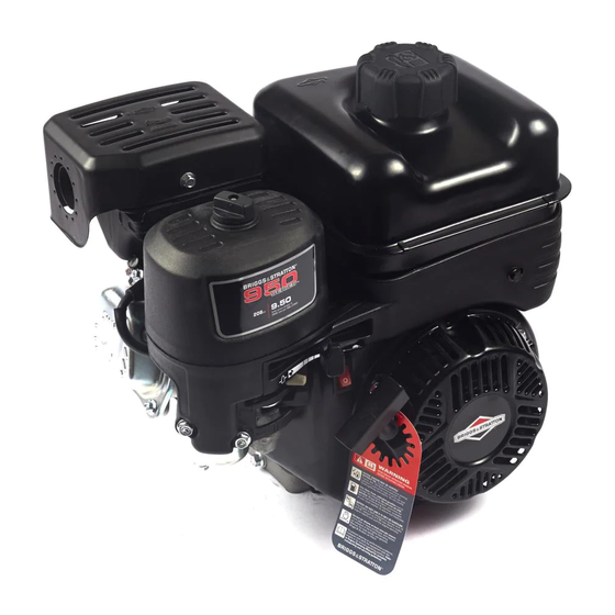
950 SERIES™ UTILITY ENGINE
MODELS:
130G00 OHV HORIZONTAL SHAFT
This APSI provides basic servicing information in advance of the repair manual under development. Systems
testing, troubleshooting, and component removal and installation procedures are common with most other
single-cylinder horizontal-shaft OHV engines. See the Illustrated Parts List for service part numbers. The
specifications, part numbers, and procedures provided here are preliminary and subject to change.
MODEL IDENTIFICATION LOCATION
The Model-Type-Trim and Code numbers (A) are printed or etched into the edge of the cylinder base below
the fuel tank. The bar code serial number label (B) is attached to the side of the fuel tank.
Copyright © Briggs & Stratton Corporation
All language translations of this document are
derived from the original English source file.
B
A
Page 1 of 13
Advertisement
Table of Contents

Related Manuals for Briggs & Stratton 950 Series


Summary of Contents for Briggs & Stratton 950 Series
- Page 1 APSI NO: DATE: AUGUST 2014 SUBJECT: 950 SERIES™ UTILITY ENGINE MODELS: 130G00 OHV HORIZONTAL SHAFT This APSI provides basic servicing information in advance of the repair manual under development. Systems testing, troubleshooting, and component removal and installation procedures are common with most other single-cylinder horizontal-shaft OHV engines.
- Page 2 OVERALL ENGINE DIMENSIONS (Millimeters) Page 2 of 13...
-
Page 3: Governor Shaft Installation
GOVERNOR SHAFT INSTALLATION There is a washer (A) that must be fitted to the governor shaft before installation into the cylinder. Secure the governor shaft from the outside with the retaining clip. The straight leg of the clip fits into the groove (B) of the governor shaft. -
Page 4: Crankcase Cover Installation
CRANKCASE COVER INSTALLATION 1) Make sure the mating surfaces on the cover and the cylinder are clean and dry. 2) Install the new gasket over the dowel pins, then carefully install the cover over the crankshaft and press into place. 3) Start the cover screws by hand and then step-torque in the sequence shown below to 220 lb-in (24.9 Nm). - Page 5 CYLINDER HEAD ASSEMBLY AND INSTALLATION 1) Install the valves, then turn the head over to install the stem seal on the intake valve. Note that the flat end of the seal faces the head. 2) Install the valve springs and retainers. 3) Position the head plate (H) with tangs facing down (inset).
-
Page 6: Stator Installation
STATOR INSTALLATION If the engine is equipped with a stator assembly, install it as follows: 1) Position the stator with the wires to the top and facing the cylinder. Feed the wires through the upper hole in the cylinder (J) and install the two screws (K). Tighten the screws to 95 lb-in (10.7 Nm). 2) Pull the stator wires tightly through the cylinder hole, then route them between the ribs as shown below. -
Page 7: Flywheel Installation
FLYWHEEL INSTALLATION 1) After installing the flywheel finger guard (L), thoroughly clean and dry the crankshaft taper. Place the flywheel key in position in the crankshaft keyway. 2) Align the keyway in the flywheel (M) to the key in the crankshaft and press the flywheel into position. 3) Install the flywheel fan (N) and the starter cup (O) to the flywheel. - Page 8 LOW-OIL MODULE INSTALLATION The low-oil module is available in either a standard 2-wire version or a lamp indicator 5-wire version. They are discussed separately below. Standard Module 2-Wire Installation 1) After connecting the wires, install the module (Q1) to the flywheel finger guard with screw. Tighten the screw to 55 lb-in (6.2 Nm).
- Page 9 Lamp Indicator Module 5-Wire Installation The wires and their associated circuits are shown below. GRN = Ground RED = Lamp Positive YEL = Oil Sensor BLK/WHT = Lamp Negative BLK1 = Remote On/Off Switch BLK2 = Ignition Coil BLK/WHT BLK2 BLK1 1) Connect the YEL wire to the oil sensor.
- Page 10 4) If equipped, attach the rocker switch ground wire under the control bracket mounting screw (R6). Complete the connections to the rocker switch as shown below. STATIC / DYNAMIC GOVERNOR ADJUSTMENT PROCEDURE IMPORTANT: The governor lever must be replaced any time the static governing is adjusted! 1) While holding throttle wide open, rotate the governor shaft clockwise until it stops.
-
Page 11: Fuel Tank Installation
FUEL TANK INSTALLATION When installing the fuel tank, the mounting screw adjacent to the control bracket must be installed first. Then the hex nuts are installed on the opposite side of the tank. Make sure the tangs of the fuel hose clamp (S) are pointing up after connecting the hose. Verify that the tank installation does not interfere with the free movement of the governor lever, link, and springs (T). -
Page 12: Fastener Torque Specifications
FASTENER TORQUE SPECIFICATIONS Fastener Torque Specs Metric Air Cleaner Base to Carburetor 40 lb-in 4.5 Nm Air Cleaner Base to Control Bracket 50 lb-in 5.6 Nm Alternator/Stator 95 lb-in 10.7 Nm Armature 95 lb-in 10.7 Nm Blower Housing 85 lb-in 9.6 Nm Carburetor Stud to Cylinder Head 60 lb-in... -
Page 13: Technical Dimensions
TECHNICAL DIMENSIONS Engineering Std Dims. Service Reject Dims. Dimensions Metric Metric Cylinder Mag Bearing Ball Ball Cam Bearing .551 in 14.00 mm .552 in 14.02 mm Bore Out-of-Round .0015 in .04 mm Cylinder Head Intake - Aluminum Valve Seat Angle 45 degrees 45 degrees Valve Stem Diameter...
Need help?
Do you have a question about the 950 Series and is the answer not in the manual?
Questions and answers
can you buy just the plastic pilot jet for thisd carb?
Stupid Q…. When checking engine oil on CR950 do you screw the dipstick back down or take the reading with the dipstick inserted but not screwed in all the way?