Table of Contents
Advertisement
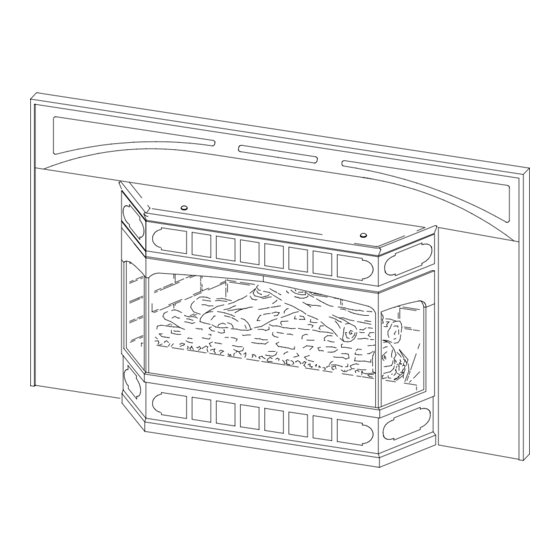
OSBURN MANDALAY SERIES
f i r e - p a r t s . c o m
WARNING: If the information in this manual is not followed exactly, a fire or explosion may result causing property
damage, personal injury, or loss of life.
For your safety
Do not store or use gasoline or other flammable vapours and liquids in the vicinity of this or any other appliance.
What to do if you smell gas
Open windows.
Extinguish any open flame.
Do not try to light any appliance.
Do not touch any electrical switch.
Do not use any phone in your building.
Immediately call your gas supplier from a neighbour's phone. Follow the gas supplier's instructions.
If you cannot reach your gas supplier call the fire department.
WARNING
Improper installation, service, adjustment, alteration, or maintenance can cause injury or property damage. Refer to this
manual. For assistance of additional information, consult a qualified installer, service agency, or the gas supplier.
Please read this manual before installing or using this appliance. Retain this manual for future reference.
Vented Fireplace Inserts
Installation and Operating Instructions
FLUSH
BAY
Made in Canada
06/03/02 MF1001
/1
Advertisement
Table of Contents

Related Manuals for Warnock Hersey MANDALAY Series


Summary of Contents for Warnock Hersey MANDALAY Series
- Page 1 OSBURN MANDALAY SERIES Vented Fireplace Inserts Installation and Operating Instructions FLUSH f i r e - p a r t s . c o m WARNING: If the information in this manual is not followed exactly, a fire or explosion may result causing property damage, personal injury, or loss of life.
-
Page 2: Table Of Contents
Page INTRODUCTION........................1 Specifications ........................1 Features .......................... 3 Intended Use ........................3 General Safety......................... 4 OPERATION..........................4 Operation Safety......................4 Lighting Instructions ......................5 Heat Output Adjustment ....................7 Fan Operation ......................... 7 Remote Control Operation....................7 INSTALLATION ........................7 Installation &... -
Page 3: Introduction
1.0 INTRODUCTION 1.1 SPECIFICATIONS TABLE 1 SPECIFICATIONS ITEM NATURAL GAS (NG) PROPANE (LPG) INPUT: 35,000 (36.9 MJ) 35,000 (36.9 MJ) AFUE: EFFICIENCY: Fan off MANIFOLD PRESSURE: 3.8” w.c. (0.9 kPa) 10.5” w.c. (2.6 kPa) GAS INLET SUPPLY PRESSURE: Minimum: 5.0” w.c. (1.2 kPa) Minimum: 11.0”... - Page 4 f i r e - p a r t s . c o m Figure 1 INSTALLATION CODES Installation must conform to local codes. In the absence of local codes, installation must conform to the National Fuel Gas Code, ANSI Z233.1 1988, (in the U.S.), or with the current installation code CAN/CGA B149.1 –...
-
Page 5: Features
1.2 FEATURES Ignition system: Standing pilot ignition system with thermopile and thermocouple flame detection and piezo igniter. Gas control: Gas control valve type: Automatic millivolt powered combination gas control valve with variable flame control for convenience and on/off switch. Optional remote on/off wall switch, optional wall thermostat, and/or optional wireless remote control are available. -
Page 6: General Safety
1.4 GENERAL SAFETY The appliance must be properly connected to a venting system in accordance with local codes. This unit must not be connected to a chimney or flue serving any other appliance. It is equipped with a safety control system to protect against improper venting of flue products. WARNING: Operation of this insert when not connected to a properly installed and maintained venting system may result in carbon monoxide poisoning. -
Page 7: Lighting Instructions
Figure 2 2.2 LIGHTING INSTRUCTIONS f i r e - p a r t s . c o m FOR YOUR SAFETY, READ BEFORE LIGHTING WARNING: If you do not follow these instructions exactly, a fire or explosion may result causing property damage, personal injury, or loss of life. A. - Page 8 LIGHTING PROCEDURE “STOP!” Red the safety information in the previous section. Set the thermostat to the lowest setting. Turn off all electrical power to the appliance. Open the access door, hinged to open downward, by gently pulling the top toward you. Push in the gas control knob slightly and turn clockwise to the “OFF”...
-
Page 9: Heat Output Adjustment
SHUTDOWN PROCEDURE To turn off the main burner only, turn off the wall switch, thermostat, or On/Off switch located on the lower right side behind the access door. For complete shutdown of the appliance, depress the gas control knob and turn it clockwise to the “OFF”... -
Page 10: Unpacking
ELECTRICAL GROUNDING NOTE: This heater fan is equipped with a three-prong (grounding) plug for your protection against shock hazard and should be plugged directly into a properly grounded three-prong receptacle. Do not cut or remove the grounding prong from this plug. WARNING: Do not connect 120 VAC (240 VAC in Australia) to the gas control valve or its wiring, as this will damage the valve. -
Page 11: Installation
3.3 INSTALLATION For satisfactory results it is necessary to plan certain aspects of the installation prior to the appliance’s final positioning. These include the vent system, the gas piping, and the fan siring. Combustible surfaces such as the hearth, mantle, and facing must also be planned for. NOTE: All Installations Require Venting. - Page 12 Minimum Clearances to Combustibles A. Sidewall 10” (254mm) measured from glass B. Ceiling 34” (864mm) measured from top grille C. Facing Sides 1” (25mm) measured from standard faceplate D. Top 8.5” (216mm) measured from the top of the grille assembly E.
-
Page 13: Chimney Liner Or Vent Installation
Figure 6 f i r e - p a r t s . c o m 3.3.2 CHIMNEY LINER OR VENT INSTALLATION Figures 7 and 8 show the completed installations into masonry and into a factory built certified fireplace. For Australia, installations and flue materials must comply with AG601 requirements. Figure 7 Figure 8... -
Page 14: Gas Line Installation
The insert must be connected to a flex liner or B-vent suitable for use with gas. The vent must run within the existing chimney from the outlet collar of the drafthood to the top of the masonry or factory built chimney. Install the vent according to the manufacturer’s instructions. Use a maximum of two offsets;... -
Page 15: Thermostat, Wall Switch, Or Remote Control Installation
3.3.4 THERMOSTAT, WALL SWITCH, OR REMOTE CONTROL INSTALLATION The burner control switch is located on the right top side of the faceplate (see Figure 2). For your convenience, the insert can also be operated by a thermostat, a wall switch, or a remote control. Millivolt thermostats and remote control kits are available from any authorized Osburn dealer. - Page 16 f i r e - p a r t s . c o m Figure 10 Figure 11...
-
Page 17: Vent, Gas Line & Wiring Connections
3.3.5 VENT, GAS LINE, & WIRING CONNECTIONS Unless it is more easily installed with the insert, install the drafthood separately first as follows: 1. Disconnect the drafthood from the insert and fit its collar to the end of the previously installed vent, whether the flue-liner is in an existing masonry fireplace or the flue-liner is in an existing factory built certified fireplace. -
Page 18: Lower Grille Installation
Figure 12 3.3.6 LOWER GRILLE INSTALLATION 1. Pull the control panel forward to release it from the retaining clips. f i r e - p a r t s . c o m 2. Remove the four screws from the firebox supports. NOTE: The Contemporary Bay (JG124) lower grille has two adapter plates attached to the grille assembly. -
Page 19: Faceplate Installation
3.3.7 FACEPLATE INSTALLATION Remove the faceplate panels and the edge trim from the packaging and assembly according to the following instructions: 1. Place the faceplate panels with the finished side down on a flat, soft, non-abrasive surface. 2. Line up the holes of the side and top panels and install the four screws loosely (see Figure 14). 3. -
Page 20: Firebox Component Installation
7. With the door removed, place the faceplate assembly up to the front of the insert. 8. Secure the faceplate with the four Philips screws (see Figure 17a). NOTE: Do not adjust the faceplate depth on the Bay Insert. FLUSH INSERT ONLY: 9. - Page 21 The front left and right logs are located by positioning them onto the positioning pins on the burner plenum (see Figure 19). Figure 19 Place the top log on top of the lower logs locating it by inserting the pins into the holes of the top log. “Y”...
- Page 22 Installing the Lower Door Trim WARNING: See sections 4.4 & 4.5 before installing the lower door trim. 1. Place the lower assembly upside down on a soft work area. 2. Remove the four retaining screws from the doorframe bottom. 3. Place the lower door trim in position over the door assembly and align the screw holes. 4.
-
Page 23: Initial Firing
FLUSH f i r e - p a r t s . c o m Figure 22 3.3.9 INITIAL FIRING When lit for the first few times, the appliance may emit an odour resulting from evaporation of paint and lubricants used in the manufacturing process. Open a door or window for ventilation. Anyone with a respiratory condition may need to leave the room during the initial firings. -
Page 24: Manifold Pressure Regulator Adjustment
Figure 23 3.3.9.1 MANIFOLD PRESSURE REGULATOR ADJUSTMENT f i r e - p a r t s . c o m The manifold pressure regulator controls gas input and flame height, and is pre-adjusted at the factory. No further adjustment is required. Manifold pressure can be verified only (see Figure 23). 3.3.9.2 PILOT FLAME ADJUSTMENT For proper operation, the pilot and main burner flames must be steady and not lifting off or floating. -
Page 25: Flue Spillage Test
3.3.9.3 FLUE SPILLAGE TEST A flue spillage test is recommended as part of this installation and should be performed by a qualified service person only. Hereafter, periodically check the vent draft. 1. Close all the doors and windows in the room. 2. -
Page 26: Altitude Adjustment
3.3.9.4 ALTITUDE ADJUSTMENT All valves have been pre-set and certified for installation at elevations from 0 – 4500 feet (1 – 1372m) above sea level. When installing this heater at higher elevations, it is necessary to decrease the input rating by replacing the existing burner orifice with a smaller size for installations over 4500 feet (1372m). -
Page 27: Glass Cleaning
4.3 GLASS CLEANING The inside of the glass may require periodic cleaning to remove deposits left from impurities in the gas and combustion air. For best results, use a ceramic glass cleaner or polish. A suitable cleaner is ® available from your dealer. Avoid the use of ammonia based cleaners such as Windex . - Page 28 Figure 26 Figure 27 f i r e - p a r t s . c o m Figure 28 7. Disconnect the remaining fan wire at the inline connector. 8. Remove the fan by first rotating it 90º backward and then sliding it forward and out. 9.
- Page 29 f i r e - p a r t s . c o m Figure 29 If necessary, the Fan Thermal Switch may be replaced as follows: 1. Turn off all electrical power to the insert; unplug power cord or turn circuit breaker off. 2.
-
Page 30: Heater Disassembly & Reassembly
4.8 HEATER DISASSEMBLY & REASSEMBLY The following procedure is to be performed by qualified service personnel ONLY. Turn off the gas supply and allow the heater to cool for up to 30 minutes. 1. Remove the top grille assembly. 2. Remove the door. 3. -
Page 31: Australian Dress Guard
5.0 AUSTRALIAN DRESS GUARD f i r e - p a r t s . c o m Figure 30... - Page 32 f i r e - p a r t s . c o m Figure 31...
-
Page 33: Trouble Shooting
6.0 TROUBLE SHOOTING SYMPTOM CORRECTIVE ACTION POSSIBLE CAUSE Pilot will not light after A. No spark at electrode (weak or not heat source for pilot ignition) repeated triggering of the red piezo ignition button 1. Improper ignition 1. Align the electrode with 1/8” (3mm) gap to pilot hood 2. - Page 34 Pilot will not stay lit after B. Defective safety circuit following the lighting 1. Loose defective 1. Check continuity, tighten wiring or instructions continued … connections connections, and repair 2. Defective electromagnet 2. Check and replace if required power unit (EPU) A.
- Page 35 III. Flame burns blue and lifts off burner 1. Insufficient combustion 1. Ensure that no foreign material blocks air being supplied inlets and that the burner shutter is correctly adjusted. Ensure the vent is adequate 2. Manifold pressure set too high 2.
-
Page 36: Replacement Parts
7.0 REPLACEMENT PARTS When requesting service or replacement parts for your insert, please provide model name, fuel type, and serial number. All parts listed below may be ordered from an authorized dealer. MANDALAY REPLACEMENT PARTS LIST COMMON PARTS COMMON PARTS PART No. - Page 37 TRADITIONAL BAY PARTS TRADITIONAL FLUSH PARTS PART No. DESCRIPTION PART No. DESCRIPTION JD064 Access Door Assembly JF107 Access Door Assembly CA109 Door Assembly (1 piece glass) JF116 Door Assembly JD035 Door Assembly (3 piece glass) JF1008 Door Trim Lower Brass JD0080 Door Trim Lower Brass JF1007...
-
Page 38: Osburn's Warranty
1700, rue Léon-Harmel, Québec (Québec) G1N 4R9 tel. : (418) 527-3060 fax : (418) 527-4311 e-mail : tech@osburn-mfg.com web site : www.osburn-mfg.com LIMITED WARRANTY The warranty of the manufacturer extends only to the original consumer purchaser and is not transferable. This warranty covers brand new products only, which have not been altered, modified nor repaired since shipment from factory.
Need help?
Do you have a question about the MANDALAY Series and is the answer not in the manual?
Questions and answers