Table of Contents
Advertisement
WARNOCK HERSEY
CERTIFIED FOR CANADA AND USA
MODEL NORTHFIRE
DVR36H/DVT36H
DIRECT VENTED BUILT-IN
GAS FIREPLACE HEATER
FOR USE WITH NATURAL GAS AND PROPANE
INSTALLATION AND OPERATING INSTRUCTIONS
FOR YOUR SAFETY
DO NOT store or use gasoline or any other flammable vapors or liquids in the vicinity
f i r e - p a r t s . c o m
of this or any other appliance
IF YOU SMELL GAS:
- Do not try to light any appliance.
- Open windows.
- Do not touch electrical switches.
- Extinguish any open flame.
- Immediately call your gas supplier from a neighbor's phone. Follow the gas supplier's
instructions.
- If you cannot reach the gas supplier, call the fire department.
PLEASE READ INSTRUCTIONS CAREFULLY BEFORE INSTALLING AND
OPERATING THE APPLIANCE
WARNING: Improper installation, adjustment, alteration, service or maintenance voids
all the manufacturer's warranties and may cause property damage, personal injury or
loss of life.
Installation and service must be performed by a qualified installer, service agency or the
gas supplier.
Installer, please leave this manual with the appliance owner for future reference.
NOT FOR USE WITH SOLID FUEL
200-0052
24JAN01
Advertisement
Table of Contents

Related Manuals for Warnock Hersey northfire dvr36h


Summary of Contents for Warnock Hersey northfire dvr36h
-
Page 1: Installation And Operating Instructions
WARNOCK HERSEY CERTIFIED FOR CANADA AND USA MODEL NORTHFIRE DVR36H/DVT36H DIRECT VENTED BUILT-IN GAS FIREPLACE HEATER FOR USE WITH NATURAL GAS AND PROPANE INSTALLATION AND OPERATING INSTRUCTIONS FOR YOUR SAFETY DO NOT store or use gasoline or any other flammable vapors or liquids in the vicinity f i r e - p a r t s . -
Page 2: Table Of Contents
CONTENTS Page Introduction General Information Appliance Description and Dimensions Installation Instructions 5 - 13 Operation Instructions 14 - 15 Maintenance Trouble Shooting Instructions 17 - 18 Servicing 19 - 20 f i r e - p a r t s . c o m Important Information Form Warranty Parts and Accessories... -
Page 3: Introduction
INTRODUCTION Thank you for purchasing the NorthFire-DVR36H/DVT36H Direct Vent Built-in Gas Fireplace Heater. The NorthFire-DV36H is one of the most advanced gas fireplace heaters on the market. It is designed using the latest technology and manufactured to the highest quality. Some of the many features are: ∗... -
Page 4: General Information
GENERAL INFORMATION APPLIANCE CERTIFICATION This appliance is listed by Warnock Hersey for use in both the United States and Canada. It is tested and certified to the following US and Canadian gas appliance standards. - ANSI Z 21.44-1995 / CAN 1-2.19-M81 Direct Vent Wall Furnaces, - ANSI Z21.50-1996 / CGA 2.22-M96, Vented Gas Fireplace and... -
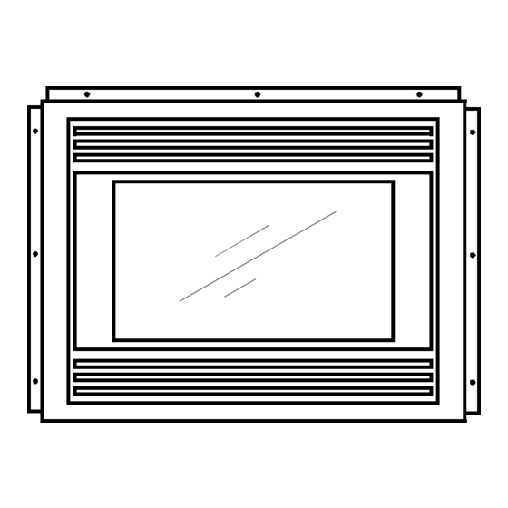
Page 5: Appliance Description And Dimensions
APPLIANCE DESCRIPTION & DIMENSIONS FRONT VIEW TOP LOUVERS GLASS DOOR CONVECTION FAN SPEED CONTROL f i r e - p a r t s . c o m GAS VALVE APPLIANCE DIMENSIONS 3/4” 36 1/4” 23 1/2” 3 1/2” 5 1/4” 37 3/4”... -
Page 6: Installation Instructions
INSTALLATION INSTRUCTIONS PRECAUTIONS • This appliance must be installed by a qualified gas installer and the installation conform to the installation codes. • Provide adequate clearance around air openings of the appliance. Never obstruct front openings. • Provide adequate clearances for proper operation and servicing of the appliance. •... - Page 7 INSTALLATION INSTRUCTIONS Cont... FRAMING DIMENSIONS 16” f i r e - p a r t s . c o m *31” 36 1/4” * If more rigidity is required. A stud may be added to the back of the top nailing flange after the fireplace is installed.
-
Page 8: Clearances To Combustibles
INSTALLATION INSTRUCTIONS Cont... CLEARANCES TO COMBUSTIBLES BACK 0” to stand-offs SIDES 0” to stand-offs 0” to stand-offs BOTTOM 0” ADJACENT SIDE WALL 1” to side of faceplate MANTLE see diagram VENT 1” to outside side and bottom surface, 2” to outside top surface. Combustible mantle allowed in shaded area. - Page 9 INSTALLATION INSTRUCTIONS Cont... VENTING Cont... VENTING CHART (FOR TOP VENTED APPLIANCES ONLY) 10 ft Venting in this area may require a vent restrictor plate #1. 7 ft 36” 30” f i r e - p a r t s . c o m 1 ft 3 ft 15 ft...
- Page 10 INSTALLATION INSTRUCTIONS INSTALLATION INSTRUCTIONS Cont... Cont... RESTRICTOR PLACEMENT “FOR ABOVE 7 FOOT VERTICAL RISE VENTED APPLICATIONS ONLY” WARNING: These restrictors are only to be installed in the vent system if the vent exceeds 7’ in vertical height, *Restrictor Number 1 below is required. Installing them under any other circumstances may cause hazardous venting conditions and may result in personal injury, property damage or death.
- Page 11 INSTALLATION INSTRUCTIONS Cont... VENTING FOR REAR VENTED APPLIANCES Maximum horizontal vent length is 2ft 6”. • Maximum of one 45º elbow is allowed. • Maintain 1” vertical rise minimum per foot of horizontal length beyond 6”. ie: no vertical • rise is required for a 6”...
- Page 12 INSTALLATION INSTRUCTIONS Cont... GLASS DOOR WARNING: Do not attempt to remove the glass door when the appliance is hot. Removing the Glass Door Remove the top and bottom louvers. There are two buckle latches securing the door frame in place (two hooks above the door and two buckle latches below the door).
- Page 13 INSTALLATION INSTRUCTIONS Cont... PLACEMENT OF LOGSET, FIBRE COALS & EMBER WOOL Place the back log at the back of the burner tray as shown, behind the two tabs on the burner • tray. A bag of fibre coals and a bag of ember wool is provided with the heater. •...
-
Page 14: Installation Instructions
INSTALLATION INSTRUCTIONS Cont... ELECTRICAL CONNECTIONS (for optional convection fan kit FK 36/38 only) Install the fan first. Remove the lower louvers and gently place the bottom front lip of the blower • mounting bracket into the opening. Slide the blower assembly into the bottom of the fireplace. Rotate the blower into position. -
Page 15: Operation Instructions
OPERATION INSTRUCTIONS FOR YOUR SAFETY, READ BEFORE LIGHTING INITIAL OPERATION • Check that the appliance is properly vented and connected to the gas supply. • Check that the logs and branches are properly placed. • Check all external parts, such as grills, door and control cover are properly attached and fastened. -
Page 16: Operation Instructions
OPERATION INSTRUCTIONS Cont.. START-UP PROCEDURE Set the thermostat, if present, to the lowest level. Set the flame adjustment knob to the HI position. Press slightly and turn the control knob clockwise to the OFF position and wait 5 minutes; thus allowing any gases to escape which may have accumulated in the combustion chamber. -
Page 17: Maintenance
MAINTENANCE CAUTION : Only conduct maintenance on a cold appliance. CLEANING THE APPLIANCE The exterior painted surfaces, glass and gold trims may be cleaned with a soft, non-abrasive cloth and water or a suitable, mild, non-abrasive cleaner. Regularly, Clean and remove any lint accumulations or debris from the grills and in any •... -
Page 18: Trouble Shooting
TROUBLE SHOOTING Please check to make sure the instructions are followed exactly before attempting trouble shooting of the appliance. WARNING: Trouble shooting and servicing of gas and electrical devices of the appliance should only be conducted by a qualified service technician. SYMPTOM ACTION Pilot will not light after pressing the... - Page 19 TROUBLE SHOOTING Cont... SYMPTOM ACTION The main burner does not turn on with 3. Check to make sure the thermostat is set high enough to turn on the appliance. the pilot lit. Cont... 4. Check that the remote switch or the thermostat is turned on. 5.
-
Page 20: Servicing
SERVICING SERVICING UNDER WARRANTY Before servicing, read the terms and conditions of the Archgard warranty at the back of the manual. Contact the Archgard authorized dealer from which you have purchased the appliance and provide him with details of the problem and the installation information which the installer has filled out at the back of the manual. - Page 21 SERVICING Cont... REPLACING MAJOR GAS COMPONENTS If any of the major gas components need to be replaced, such as the pilot or the gas valve, we recommend replacing the complete gas component assembly. The assembly is designed to be quickly and easily repaired with minimal inconvenience to the customer Replacing Gas Component Assembly Disconnect electricity to the appliance.
-
Page 22: Important Information
IMPORTANT INFORMATION * Please have the installer fill-out the installation information for warranty and future reference. APPLIANCE MODEL NUMBER NORTHFIRE- DVR36H/ DVT36H SERIAL NUMBER GAS TYPE NATURAL GAS VALVE TYPE SIT 820 DATE PURCHASED OWNER NAME ADDRESS CITY STATE/PROVINCE f i r e - p a r t s . c o m COUNTRY ZIP/POSTAL CODE... -
Page 23: Warranty
ARCHGARD LIMITED WARRANTY This Limited Warranty is made by ARCHGARD INDUSTRIES LTD. hereinafter referred to as "ARCHGARD ". Archgard guarantees to the original consumer that the combustion chamber of its gas burning fireplaces will be free from defects in materials and workmanship under normal use and service, for a lifetime. -
Page 24: Replacement Parts
REPLACEMENT PARTS NORTHFIRE-DV36H DIRECT VENTED BUILD-IN GAS FIREPLACE DESCRIPTION PART # GAS COMBINATION VALVE ( REMOTE ) - NG 308-0013 GAS COMBINATION VALVE ( REMOTE ) - LP 308-0012 PILOT ASSEMBLY WITH PIEZO ELECTRODE ( REMOTE ) - NG 308-0055 PILOT ASSEMBLY WITH PIEZO ELECTRODE ( REMOTE ) - LP 308-0054 THERMOCOUPLE... - Page 25 f i r e - p a r t s . c o m 24 24...
-
Page 26: Warranty Registration
Postage WARRANTY REGISTRATION ARCHGARD INDUSTRIES LTD. 7116 BEATTY DRIVE MISSION, B.C. CANADA V2V 6B4 FOLD DOWN AT LINE f i r e - p a r t s . c o m FOLD DOWN AT LINE & TAPE CLOSED Model No:____________________________ Date Installed: _____/_____/______ Name &...
Need help?
Do you have a question about the northfire dvr36h and is the answer not in the manual?
Questions and answers