Advertisement
Quick Links
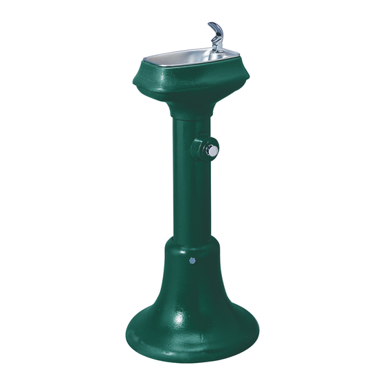
Halsey Taylor Owners Manual
Models 4880 and 4881 (30" and 36")
Freeze Resistant Floor Mount Fountains
Installer
To assure you install this model easily and correctly,
PLEASE READ THESE SIMPLE INSTRUCTIONS BEFORE STARTING THE
INSTALLATION. CHECK YOUR INSTALLATION FOR COMPLIANCE WITH
PLUMBING, ELECTRICAL AND OTHER APPLICABLE CODES. After installation, leave
these instructions inside the fountain for future reference.
ALL SERVICE TO BE PERFORMED BY AN AUTHORIZED SERVICE PERSON
IMPORTANT! INSTALLER PLEASE NOTE.
THE GROUNDING OF ELECTRICAL EQUIPMENT SUCH AS TELEPHONE, COMPUTERS, ETC. TO WATER LINES
IS A COMMON PROCEDURE. THIS GROUNDING MAY BE IN THE BUILDING OR MAY OCCUR AWAY FROM THE
BUILDING. THIS GROUNDING CAN CAUSE ELECTRICAL FEEDBACK INTO A FOUNTAIN, CREATING AN ELEC-
TROLYSIS WHICH CAUSES A METALLIC TASTE OR AN INCREASE IN THE METAL CONTENT OF THE WATER.
THIS CONDITION IS AVOIDABLE BY USING THE PROPER MATERIALS AS INDICATED. ANY DRAIN FITTINGS
PROVIDED BY THE INSTALLER SHOULD BE MADE OF PLASTIC TO ELECTRICALLY ISOLATE THE FOUNTAIN
FROM THE BUILDING PLUMBING SYSTEM.
General Installation Tips
1. Be sure to flush water supply line before you connect it to the inlet fitting on Freeze Resistant Valve System.
2. There are two drain lines required for this unit. One for the drinking fountain basin drain and one for the valve/water
supply line system. The bowl drain is the 3/4" PVC fitting at the bottom of the 6" PVC tube and the valve drains
through the small holes in the PVC cap. Provide ample drainage for these two items. It's always better to have too
much then not enough.
3. The column (6" PVC tube) must remain vertical. Be sure it remains vertical when backfilling the excavating trench.
4. When the concrete pad, for mounting the fountain, is poured, be sure to allow adequate space around the top of the
column so that the flexible cap may be removed for servicing the valve
5. We recommend that the top of the column be flush or slightly above the top height of the concrete pad.
6. You should test the unit before you backfill. Simply blow on the clear, small diameter tubing. A steady stream should
flow from the braided tubing line. When air pressure is removed from the clear tubing the water stream should stop.
7. Once you have tested the valve, backfilled the hole and poured the concrete mounting pad you are ready to set the
fountain. After bolting the fountain in place connect the air control valve tubing, supply water tubing and drain lines
The water supply line must have a straight run from the basin bubbler down to the control valve. If a straight run is
not maintained water will become trapped and freeze leaving the unit inoperable. Test the fountain again. If it fails
to work, the air control line may be kinked or connected improperly. Be sure to keep water out of the air control line.
8. These products are designed to operate on 20 psig to 105 psig supply line pressure. If inlet pressure above 105
psig, a pressure regulator must be installed in the supply line. Any damage caused by reason of connecting this
product to supply line pressure lower than 20 psig or higher than 105 psig is not covered by warranty.
IMPORTANT:
Do not pull up on lines coming out of the PVC column. This raises the water valve above the frost line
with disastrous results.
IMPORTANT
PAGE 1
96967C (Rev. E - 8/09)
Advertisement

Related Manuals for Halsey Taylor 4880


Summary of Contents for Halsey Taylor 4880
- Page 1 Halsey Taylor Owners Manual Models 4880 and 4881 (30" and 36") Freeze Resistant Floor Mount Fountains Installer To assure you install this model easily and correctly, PLEASE READ THESE SIMPLE INSTRUCTIONS BEFORE STARTING THE INSTALLATION. CHECK YOUR INSTALLATION FOR COMPLIANCE WITH PLUMBING, ELECTRICAL AND OTHER APPLICABLE CODES.
- Page 2 Installation Instructions 1. Prepare trench for water supply and waste drain lines (if required by local codes). The hole should be deep enough to accommodate the PVC column and 5 cubic feet of porous fill (large broken rock). Additional porous fill may be required due to local ground conditions. (See ground Rough-in Detail Page 4) 2.
- Page 3 BACK FILL (DIRT) PAGE 3 96967C (Rev. E - 8/09)
- Page 4 14, 27 WATER LINE DRAIN LINE 16, 17, 19 Concrete Slab (By Installer) PARTS LIST ITEM NO. PART NO. DESCRIPTION 100322740560 Gasket-Black 160351543730 Waste Pipe 1" O.D. x 16.50 160016143730 Waste pipe 1" O.D. x 22.50 56092C Poly Tubing - 1/4" (Cut to Length) - To Bubbler 15013C Bubbler Tube Assy.
Need help?
Do you have a question about the 4880 and is the answer not in the manual?
Questions and answers