
Related Manuals for Jolly Mec Control Display

Summary of Contents for Jolly Mec Control Display
- Page 1 CONTROL DISPLAY USER MANUAL To be kept by the purchaser Control display for water heating products...
- Page 2 Dear Customer, thank you for having chosen to heat and save with a Jolly Mec product. Please carefully read and keep this sheet before using the equipment. The manual provides information and suggestions necessary for correct product use. Knowing and observing these...
-
Page 3: Table Of Contents
TABLE OF CONTENTS CHAP.01 PREMISES........................... 4 01.1 WARNINGS ..............................4 01.2 SYMBOLOGY ............................... 4 CHAP.02 USER INTERFACE ........................5 02.1 CONTROL DISPLAY DESCRIPTION ......................5 02.2 KEY FUNCTIONS ............................5 02.3 ICON MEANINGS ............................6 CAP.03 OPERATING MODE ........................6 03.1 APPLIANCE OPERATIONS ......................... -
Page 4: Chap.01 Premises
CHAP.01 PREMISES 01.1 WARNINGS • We recommend you carefully read and follow the instructions in this manual for correct use. • It should be kept with care and attentively consulted since all the warnings provide important safety instructions. • Incorrect use could cause damage and injury to people, animals or property, for which the manufacturer cannot not be held liable. • The appliance must be used only for its intended purpose. Any other use is deemed improper and therefore dangerous. • The manufacturer declines any contractual or non-contractual liability for damages caused by errors in installation or use of the appliance or failure to follow the instructions contained in this manual. • All rights on the reproduction of this technical manual are owned by Jolly Mec Caminetti S.p.A. • The descriptions and illustrations provided in the following publication are not binding. • Jolly Mec Caminetti S.p.A reserves the right to make any modifications that may be deemed appropriate. • This manual cannot be given to third parties for perusal without the written permission of Jolly Mec Caminetti S.p.A. • Do not make any unauthorised modification to the appliance. Any unauthorised modification will automatically invalidate the warranty and release the manufacture from all liability. • Use only original spare parts recommended by the manufacturer. Original spare parts are available through retailers, specialised Tecnical Service Centers, or directly at the head office of Jolly Mec Caminetti S.p.A. 01.2 SYMBOLOGY In this manual, points of considerable importance are marked with the following symbology: INSTRUCTION: Instructions regarding the correct use of the appliance. -
Page 5: Chap.02 User Interface
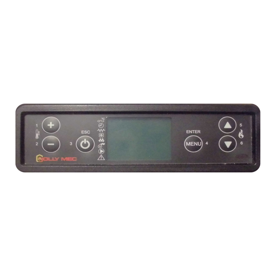
CONTROL DISPLAY DESCRIPTION The control display lets you communicate with the control unit. The keys are used to transmit commands to the control unit while the display informs the user on stove operating status. Programming mode displays the various settings that can be edited using the keys. -
Page 6: Icon Meanings
02.3 ICON MEANINGS A segment may or may not be found next to each icon on the display to indicate whether or not the relevant component and/or function is enabled. The functions or components associated with the various icons are: Room probe request Auger gear motor Chronothermostat... -
Page 7: Main Status Message Meanings
03.2 MAIN STATUS MESSAGE MEANINGS During normal operations, the screen displays the time, room temperature, water temperature and a message that indicates device status when the message is displayed. An illustration of the main display screen appears below. The main messages that can appear on the display and their meanings are summarised in the following table: MESS- Description TEXT... -
Page 8: Main Settings
03.3 MAIN SETTINGS Use the specific keys on the control display to directly access from the main page the room, stove and, according to the adopted system configuration, the puffer and/or boiler output and temperature settings pages. Output settings To change the operating output, press Key 5 on the main page to immediately open the screen where you can use the Keys 5 or 6 to select from the five settable output settings. -
Page 9: Chap.04 User Menu
CHAP.04 USER MENU 04.1 FUNCTIONS The display is divided into menus and sub-menus that can be scrolled using the control display keys. In short, main menus and their functions are: MENU Description 1 - SET CLOCK Lets you set the current date and time, required for correct chronothermostat operations 2 - SET CHRONO Lets you turn the chronothermostat and its programs on or off. -
Page 10: Structure
04.2 STRUCTURE To open the various menus, press Key 4 when the main page is displayed on the remote control. To scroll the various menu pages, use Keys 5 and 6. MENU 1 - SET CLOCK M1-001 DAY To select the current day of the week, use Keys 1 and 2 and press Key 4 to set the displayed value and move to the next page. - Page 11 MENU 2 - SET CHRONO M2-1 DELAY Lets you set a switch-on or shutdown delay time. M2-2 ENABLE CHRONO Lets you turn the chronothermostat function on or off. M2-3 PROGRAM DAY Lets you set two time ranges enabled every day of the week.
- Page 12 M2-2-001 ENABLE CHRONO Use Keys 1 and 2 to select to enable or disable the chronothermostat function and press Key 4 to confirm the selection and move to the next page. This function can be accessed more rapidly by Keys 1 and 2 on the main page.
- Page 13 M2-4-001 CHRONO WEEK Use Keys 1 and 2 to select to enable or disable the CHRONO WEEK function and press Key 4 to confirm the selection and move to the next page. M2-4-002 START PROG- 1 Use Keys 1 and 2 to set the start time for the first operating time range permitted by the function and press Key 4 to confirm the selection and move to the next page.
- Page 14 M02-05-001 CHRONO WEEK-END Use Keys 1 and 2 to select to enable or disable the CHRONO WEEK-END function and press Key 4 to confirm the selection and move to the next page. M02-05-002 START 1 WEEK-END Use Keys 1 and 2 to set the start time for the first operating time range permitted by the function and press Key 4 to confirm the selection and move to the next page.
- Page 15 MENU 4 - SET PROBE M4-001 PROBE Use Keys 1 and 2 to select the required probe type from those available (PROBE, THERMOST) and press Key 4 to confirm. When finished, the message DONE will be displayed to confirm correct data entry. Next, the level page automatically returns to the Menu Page.
- Page 16 MENU 6 - SET DISPLAY M6-001 SET BUZZER Use Keys 1 and 2 to mute the buzzer when alarms occur and press Key 4 to confirm and move to the next page. In this case, no buzzer will sound when the stove malfunctions.
- Page 17 MENU 8 - STATE STOVE M8-001 TEMP FUME Fume temperature is displayed in this page. M8-002 FUME SPEED Fume fan speed (rpm) is displayed in this page. M8-003 AUGER ON TIME Pellet load auger operating time is displayed in this page.
- Page 18 M8-011 BOARD TEMP- Electronic board temperature is displayed in this page. M8-011 PELLET TEMP- Safety temperature is displayed in this page. M8-012 ZONE MODULE 1 Zones in request in the first zone module are displayed in this page. M8-012 ZONE MODULE 2 Zones in request in the second zone module are displayed in this page.
- Page 19 M8-022 STATE STOVE Appliance status is displayed in this page. MENU 9 - TECHNIC SETTINGS Password protected Menu reserved to the Jolly Mec Customer Service (CAT) technician. NOTE The service technician can update all stove functional settings in MENU 9 - TECHNIC SETTINGS. Each...
- Page 20 MENU A - REGULATE SETTING MA-001 REGULATE PELLET Use Keys 1 and 2 to adjust the quantity of pellets between -09 and -09 corresponding to ±3% each unit and press Key 4 to confirm and move to the next page. MA-002 REGULATE CHIMNEY Use Keys 1 and 2 to adjust fume exhaust speed between -09 and -09 corresponding to ±3% each unit and press...
- Page 21 Mb-005 WORK PWR HOURS The number of appliance working hours is displayed in this page. Work hours refers to the total of the 5 outputs and eco output. Mb-006 ECO PWR HOURS The number of working hours in ECONOMY mode is displayed in this page.
- Page 22 Mb-020 BATCH The product lot number is displayed in this page. Mb-021 SERIAL N The product serial number is displayed in this page. Mb-021 FILE The control unit program file name is displayed in this page. NOTE When the counter reaches a value of 9999, displayed on the first row, the next increase will reset the first row counter and increase by one unit the counter on row three next to the HOURS message.
-
Page 23: Chap.05 Fault Diagnosis And Troubleshooting
CHAP.05 FAULT DIAGNOSIS AND TROUBLESHOOTING 05.1 ALARM MESSAGES Following is an overview on appliance alarms linked to the probable causes and some potential solutions. If an alarm occurs with a certain frequency, contact the specialised Technical Service Center.. Alarm alert screens appear as illustrated below: Alarm code Alarm text Alarm causes... - Page 24 Alarm code Alarm text Alarm causes Main solutions AL06 • The fumes temperature drops below the Pr47 • Pellet tank empty, top up. NO MORE value. • Adjust pellet flow and fume exhaust fan speed to PELLET keep minimum flame. •...
- Page 25 Alarm code Alarm text Alarm causes Main solutions • Electronic board temperature has exceeded the • Make sure room aeration is correct. AL15 M-BOARD safety threshold. • Check appliance operating settings, they could SECURITY generate excessive overheating in the machine body.
- Page 26 NOTES...
- Page 28 Via S.Giuseppe 2 - 24060 Telgate (Bg) Italy Tel. +39 035.83.59.211 Fax +39 035.83.59.203 www.jolly-mec.it - info@jolly-mec.it...
Need help?
Do you have a question about the Control Display and is the answer not in the manual?
Questions and answers