Table of Contents
Advertisement
FLXMOD MST S4 series
Smitec S.p.A., viale Vittorio Veneto 4, 24016 San Pellegrino Terme (BG), Italy, www.smitec.it
Installation, use and maintenance manual
BEFORE STARTING UP THE INDUSTRIAL PC OF FLXMOD MST S4 SERIES, CARE-
FULLY READ THIS MANUAL AND FOLLOW ALL INSTRUCTIONS, IN ORDER TO EN-
SURE MAXIMUM SAFETY
WITH SERCOS III BUS MASTER
FLXMOD MST S4 SERIES
The technical data and the drawings in this manual might have been modified later; always
refer to the latest version.
Ver. 1.01
INDUSTRIAL PCs
Installation, use and maintenance manual - EN
1
Advertisement
Table of Contents

Subscribe to Our Youtube Channel
Related Manuals for Smitec FLXMOD MST S4 Series


Summary of Contents for Smitec FLXMOD MST S4 Series
- Page 1 FLXMOD MST S4 series Installation, use and maintenance manual - EN Smitec S.p.A., viale Vittorio Veneto 4, 24016 San Pellegrino Terme (BG), Italy, www.smitec.it Installation, use and maintenance manual BEFORE STARTING UP THE INDUSTRIAL PC OF FLXMOD MST S4 SERIES, CARE-...
-
Page 2: Table Of Contents
FLXMOD MST S4 series Installation, use and maintenance manual - EN Summary 3 Preface ............................... 3 4 General warnings ............................4 5 Safety instructions ............................ 6 5.1 General information ..........................6 5.2 Precautions during handling and assembly ..................6 6 Product description ..........................7 6.1 Pictures of MST S4 module ....................... -
Page 3: Preface
FLXMOD MST S4 series Installation, use and maintenance manual - EN 3 Preface This manual provides all necessary information for the installation, use and maintenance of FLXMOD MST S4 modules. The instructions included in this manual are addressed to the following professionals:... -
Page 4: General Warnings
MANUAL. THE EQUIPMENT CANNOT BE USED FOR PURPOSES DIFFERENT THAN THE ONES DESCRIBED IN THIS MANUAL; SMITEC S.p.A. SHALL NOT BE HELD RESPONSIBLE FOR ANY DAMAGES, INCON- VENIENCES OR ACCIDENTS DUE TO THE NON-COMPLIANCE WITH THESE PRESCRIPTIONS. In order to make the manual consultation easier, the following symbols have been adopted: Indication of “PROHIBITED ACTION”. - Page 5 FLXMOD MST S4 series Installation, use and maintenance manual - EN The safety prescriptions aim at establishing a series of behaviors and obligations to be complied with, while performing the activities described later on in this manual. These prescriptions constitute the prescribed method of operating the device, in a way that is safe for person- nel, equipments and environment.
-
Page 6: Safety Instructions
It is absolutely forbidden to use the equipment for different purposes than the ones de- scribed in this manual. The technical data and the drawings in this manual might have been modified later; always refer to the latest version. All upgrades can be requested to SMITEC S.p.A. directly. -
Page 7: Product Description
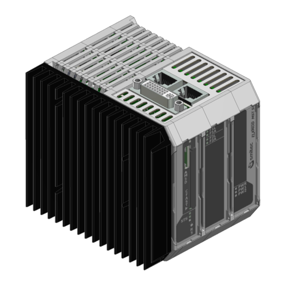
FLXMOD MST S4 series Installation, use and maintenance manual - EN 6 Product description The MST S4 module is an industrial PC based on an Intel® 64 architecture with integrated SERCOS III bus master. Housed in a very compact plastic case, it has been designed to be installed on a standard DIN rail and to be perfectly integrated in a FLXMOD automation system. - Page 8 FLXMOD MST S4 series Installation, use and maintenance manual - EN Ver. 1.01...
-
Page 9: Technical Data
All the technical data in this section correspond to the hardware configuration of the MST S4 manufactured on the date when this manual was drawn up. To improve or update this product, SMITEC S.p.A. reserves the right to modify its technical features without notice. 7.1 Environmental specifications Operating temperature 0°... -
Page 10: Mechanical Specifications
FLXMOD MST S4 series Installation, use and maintenance manual - EN 7.3 Mechanical specifications Fastening Installed on standard DIN rail Weight 530g 7.3.1 Mechanical dimensions 7.3.1.1 Front view Ver. 1.01... - Page 11 FLXMOD MST S4 series Installation, use and maintenance manual - EN 7.3.1.2 Rear view Ver. 1.01...
- Page 12 FLXMOD MST S4 series Installation, use and maintenance manual - EN 7.3.1.3 Top view Ver. 1.01...
- Page 13 FLXMOD MST S4 series Installation, use and maintenance manual - EN 7.3.1.4 Bottom view Ver. 1.01...
-
Page 14: Hardware Features
FLXMOD MST S4 series Installation, use and maintenance manual - EN 7.4 Hardware features The below features correspond to the hardware minimum configuration supplied with the product and tested from a functional point of view; any additional peripheral unit eventually available in the actual product is not guaranteed, neither from an operational nor from a functional point of view. -
Page 15: Order Codes
FLXMOD MST S4 series Installation, use and maintenance manual - EN 7.5 Order codes Order code Model Description KZ010512 MST S402 FLXMOD - MST S4 - DIAGOS+FLXCORE (ST) KZ010516 MST S4 FLXMOD - MST S4 - FLXCORE (ST) KZ010607 MST S402 FLXMOD - MST S4 - FLXCORE (ST) 7.6 Accessories... -
Page 16: Connections And Leds
FLXMOD MST S4 series Installation, use and maintenance manual - EN 8 Connections and LEDs 8.1 Front view CFAST LED CFAST (Reset button) Connection references 8.1.1 Name Function Socket for CFast memory CFAST Socket for micro SD memory Signalling LEDs 8.1.2... -
Page 17: Top View
FLXMOD MST S4 series Installation, use and maintenance manual - EN It indicates successful connection with port 1 through protocol Sercos III It indicates data exchange with port 1 through protocol Sercos III It indicates successful connection with port 2 through protocol Sercos III... -
Page 18: Bottom View
FLXMOD MST S4 series Installation, use and maintenance manual - EN 8.3 Bottom view 24VIN ETH1 ETH2 8.3.1 Connection references Name Function ETH1 Ethernet communication port 1 ETH2 Ethernet communication port 2 USB 3.0 port 24VIN Input for 24VDC main power supply... -
Page 19: In Supply Connector
FLXMOD MST S4 series Installation, use and maintenance manual - EN 8.3.2 24V IN supply connector The connector which powers the MST S4 module features spring contacts, in order to make the wiring of single cables easier. Connector type: Phoenix Contact FKCT 2,5/4-ST (1910377) -
Page 20: Sercos Iii Connectors
FLXMOD MST S4 series Installation, use and maintenance manual - EN Use an adequately sized wire, according to the current flowing. A lower cross-section might cause fire, due to overheating caused by the wire. In order to meet the requirements of the EMC 2014/30/UE, the cable must not be longer than 30 meters. -
Page 21: Usb Port
FLXMOD MST S4 series Installation, use and maintenance manual - EN 8.5 USB port The USB connector is located on the underside of the module. The type of connector used is the most common type: type A USB 3.0. The USB 3.0 port is compatible with the USB 2.0 standard. -
Page 22: Led Behavior Of Communication Speed Signaling
FLXMOD MST S4 series Installation, use and maintenance manual - EN 8.6.1 LED behavior of communication speed signaling Below is a table that summarizes the possible speed states of the Ethernet ports: Name State Function Ethernet port S1 communicating at a speed equal to 10 Mbps... -
Page 23: Housing Socket Of Cfast Card Memory And Micro Sd (Msd) Memory
FLXMOD MST S4 series Installation, use and maintenance manual - EN 8.7 Housing socket of CFast card memory and micro SD (MSD) memory The sockets for the CFast memory and for the SD memory are located on front of the device. These memories are installed inside the device, behind a transparent plastic cover. -
Page 24: Installation
FLXMOD MST S4 series Installation, use and maintenance manual - EN Installation During installation of the FLXMOD MST S4 computer, falls and violent shocks must be avoided which could compromise the smooth operation. Avoid touching the input / output connectors on the computer panel directly unless you are equipped with suitable static electricity protection equipment;... -
Page 25: Environmental Requirements
FLXMOD MST S4 series Installation, use and maintenance manual - EN DIN rail 9.2 Environmental requirements In order for the system to operate properly, the MST S4 module must remain within the temperature limits in- dicated in the specifications. This means that, inside the electrical cabined where the module is installed, there should be a suited cooling system in order to keep the temperature within the correct limits. -
Page 26: Use
FLXMOD MST S4 series Installation, use and maintenance manual - EN 10 Use 10.1 CFast card The CFast card of the MST S4 module replaces the traditional hard disk, thus ensuring better shock tolerance and longer life of the device, also in case of continuous working cycles. -
Page 27: Priority Of The Start-Up Devices
FLXMOD MST S4 series Installation, use and maintenance manual - EN 10.3 Priority of the start-up devices A boot device is the CFast card or USB flash disk, or other mass storage on which the operating system (for example Windows) is stored by which the computer boots. -
Page 28: Ordinary Maintenance
FLXMOD MST S4 series Installation, use and maintenance manual - EN 11 Ordinary maintenance 11.1 Clock battery replacement The backup battery in the MST S4 module powers the RTC circuit (real-time clock). The RTC is a real-time clock which remains active even when the device is off and constantly updates the date and time. According to the ambient temperature and to the computer use, the battery can have a markedly different duration, start- ing from the MST S4 production date. - Page 29 FLXMOD MST S4 series Installation, use and maintenance manual - EN • STEP 2 With a tweezers, gently lift the silk-screened plastic plate and remove it Ver. 1.01...
- Page 30 FLXMOD MST S4 series Installation, use and maintenance manual - EN • STEP 3 Gently remove the battery with pliers, being careful not to drop it into the device Insert the battery in the housing indicated in the figure, paying attention to the polarity and then to the direction in which the battery is inserted.
-
Page 31: Appendices
FLXMOD MST S4 series Installation, use and maintenance manual - EN 12 Appendices 12.1 Appendix I: CMOS Setup parameters In the MST S4 module, the CMOS Setup parameters are stored in the BIOS and are password protected to guarantee operation. -
Page 32: Analytical Index
FLXMOD MST S4 series Installation, use and maintenance manual - EN 13 Analytical index Absorbed current ..........9 SERCOS III ..........7, 20 Absorbed power..........9 Sercos III ............20 Altitude ............... 9 Architecture............14 Assembly ............24 Weight ............. 10 Basic Hardware..........
Need help?
Do you have a question about the FLXMOD MST S4 Series and is the answer not in the manual?
Questions and answers
Estou tendo problemas com o módulo CPL S3
Issues that can occur with the Smitec MST S4 Series module include:
1. Damage from static electricity if input/output connectors are touched without proper protection.
2. Damage or operator danger if electrical connections are made while the device is powered on.
3. Improper grounding of connected devices may cause damage or danger.
4. Difficulty disconnecting wiring if the device is poorly positioned.
5. Loss of CMOS setup parameters if the buffer battery runs out, requiring manual date and time reset.
6. Risk of incorrect assembly if not properly mounted on a DIN rail.
This answer is automatically generated