Table of Contents
Advertisement
Advertisement
Table of Contents

Related Manuals for Miller FILTAIR MWX-S


Summary of Contents for Miller FILTAIR MWX-S
- Page 1 OM-239026K 2019-09 Processes Multiprocess Welding Description Mobile Weld Fume Extractor FILTAIR ® MWX-S Mobile Weld Fume Extractor Read And Save These Instructions OWNER’S MANUAL For product information, Owner’s Manual translations, and more, visit www.MillerWelds.com...
- Page 2 We know you don’t have time to do it any other way. That’s why when Niels Miller first started building arc welders in 1929, he made sure his products offered long-lasting value and superior quality.
-
Page 3: Table Of Contents
TABLE OF CONTENTS SECTION 1 – SAFETY PRECAUTIONS – READ BEFORE USING..............1 Symbol Usage . -
Page 5: Section 1 - Safety Precautions - Read Before Using
SECTION 1 – SAFETY PRECAUTIONS – READ BEFORE USING Protect yourself and others from injury—read, follow, and save these important safety precautions and operating instructions. 1-1. Symbol Usage DANGER! – Indicates a hazardous situation which, if not � Indicates special instructions. avoided, will result in death or serious injury. -
Page 6: Arc Welding And Plasma Cutting Hazards
ELECTRIC SHOCK can kill. MOVING PARTS can injure. Touching live electrical parts can cause fatal � Keep hands, hair, loose clothing, jewelry, tools, shocks or severe burns. The input power circuit and other objects away from moving parts such as and machine internal circuits are also live when fans. - Page 7 � Insulate work clamp when not connected to workpiece to prevent WELDING AND CUTTING can cause contact with any metal object. fire or explosion. � Do not connect more than one electrode or work cable to any sin- Welding or cutting on closed containers, such as gle weld output terminal.
-
Page 8: Additional Symbols For Installation, Operation, And Maintenance
� Keep protective cap in place over valve except when cylinder is in CYLINDERS can explode if use or connected for use. damaged. � Use the proper equipment, correct procedures, and sufficient Compressed gas cylinders contain gas under high number of persons to lift, move, and transport cylinders. pressure. -
Page 9: California Proposition 65 Warnings
� Perform installation, maintenance, and service according to the COMPRESSED AIR can injure or kill. Owner’s Manuals, industry standards, and national, state, and lo- cal codes. � Before working on compressed air system, turn off and lockout/tagout unit, release pressure, and be sure air pressure cannot be accidentally applied. -
Page 10: Emf Information
1-7. EMF Information Electric current flowing through any conductor causes localized elec- 4. Keep head and trunk as far away from the equipment in the weld- tric and magnetic fields (EMF). The current from arc welding (and al- ing circuit as possible. lied processes including spot welding, gouging, plasma arc cutting, 5. -
Page 11: Section 2 - Consignes De Sécurité - Lire Avant Utilisation
SECTION 2 – CONSIGNES DE SÉCURITÉ - LIRE AVANT UTILISATION Pour écarter les risques de blessure pour vous-même et pour autrui — lire, appliquer et ranger en lieu sûr ces consignes relatives aux précautions de sécurité et au mode opératoire. 2-1. -
Page 12: Dangers Du Soudage À L'arc Et Du Coupage Au Plasma
e. Si vous croyez que l’équipement ne procure pas une protection LA CHUTE DE L’ÉQUIPEMENT peut adéquate. provoquer des blessures. � Ne pas réparer, modifier ou démonter l’extracteur de fumées ou l’utiliser avec des pièces ou accessoires non fournis par le fabri- �... - Page 13 � D’autres consignes de sécurité sont nécessaires dans les condi- � Ne pas toucher aux pièces chaudes, utiliser les outils recom- tions suivantes : risques électriques dans un environnement hu- mandés et porter des gants de soudage et des vêtements épais mide ou si l’on porte des vêtements mouillés ;...
- Page 14 Le SOUDAGE ET le COUPAGE DES PIECES DE METAL ou DES présentent un risque d’incendie SALETES peuvent provoquer des ou d’explosion. blessures dans les yeux. Le soudage ou le coupage effectué sur des conte- � Le soudage, l’écaillement, le passage de la pièce neurs fermés, tels que réservoirs, tambours ou à...
-
Page 15: Dangers Supplémentaires En Relation Avec L'installation, Le Fonctionnement Et La Maintenance
� Les porteurs d’implants médicaux doivent consulter leur médecin Les CHAMPS et le fabricant du dispositif avant de s’approcher de la zone où se ÉLECTROMAGNÉTIQUES (CEM) déroule du soudage à l’arc, du soudage par points, du gougeage, peuvent affecter les implants de la découpe plasma ou une opération de chauffage par induction. -
Page 16: Proposition Californienne 65 Avertissements
� Pour rechercher des fuites, utiliser de l’eau savonneuse ou un dé- LE RAYONNEMENT HAUTE tecteur à ultrasons, jamais les mains nues. En cas de détection de FRÉQUENCE (H.F.) risque de fuite, ne pas utiliser l’équipement. provoquer des interférences. � Remettre les portes, panneaux, recouvrements ou dispositifs de protection quand l’entretien est terminé... -
Page 17: Informations Relatives Aux Cem
Applications Manual for the Revised NIOSH Lifting Equation, The Na- Fume 2019–02 tional Institute for Occupational Safety and Health (NIOSH), 1600 Clif- ton Rd, Atlanta, GA 30329-4027 (phone: 1-800-232-4636, website: www.cdc.gov/NIOSH). 2-7. Informations relatives aux CEM 3. Ne pas courber et ne pas entourer les câbles autour de votre Le courant électrique qui traverse tout conducteur génère des champs électromagnétiques (CEM) à... -
Page 19: Section 3 - Definitions
SECTION 3 – DEFINITIONS SECTION 3 − DEFINITIONS 3-1. Miscellaneous symbol definitions 3-1. Symbols And Definitions Percent Line Connection Protective Earth Percent Air Filter (Ground) Primary Voltage Alternating Current Amperes Volts Air Filter Protective Earth Rated Supply (AC) Amperage (Ground) Current Input Plug And Rated Supply... -
Page 20: Section 4 - Specifications
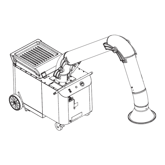
SECTION 4 SPECIFICATIONS SECTION 4 – SPECIFICATIONS 4-1. General Description The MWX-S weld fume collector is a mobile, high-volume vacuum system that uses a high efficiency, nanofiber-media cartridge filter to collect airborne 4-1. General Description weld fume particles. Weld fumes are captured at the source by a unit-mounted extraction arm. The extraction arm uses locking joints and flexible tubing to ensure the hood is placed near the source of the fumes. -
Page 21: Section 5 - Installation
5-1. Serial Number And Rating Label Location The serial number and rating information is located on the front of the unit. Use rating label to determine input power requirements and/or rated output. For future reference, write serial number in space provided on back cover of this manual. SECTION 5 –... -
Page 22: Tipping
5-2. Tipping 5-3. Tipping Do not move or operate unit where Do not move or operate unit it could tip. where it could tip. Do not move unit with extraction Do not move unit with extrac- arm extended or unit may tip. tion arm extended or unit Do not move unit by pulling on ex- may tip. -
Page 23: Connecting To Compressed Air Supply
5-4. Connecting to Compressed Air Supply 805268 5-5. Connecting To Compressed Air Supply Shut off air supply before disconnecting or connecting Shut off air supply before discon- air hose. necting or connecting air hose. Wear protective equipment Wear protective equipment when when disconnecting com- disconnecting compressed... -
Page 24: Section 6 - Operation
SECTION 6 – OPERATION SECTION 6 OPERATION 6-1. Controls 6-1. Controls Only use the fume extractor to ex- tract weld fumes. Do not use the fume extractor to extract hot gases (above 140° F/60° C), wood or ce- ment dust, engine exhaust, liquid vapors, explosive materials, ag- gressive fumes (acid), fumes from burning objects, or fumes from... -
Page 25: Prestart Checklist (Before Welding)
6-2. Prestart Checklist (Before Welding) 6-2. Prestart Checklist (Before Welding) Do not use the fume extrac- tion equipment unless you are sure it is correctly as- sembled working properly. Check for free and easy move- Do not use the fume extraction equipment unless you are sure it is ment of the extraction arm and swivel base before each use. -
Page 26: Section 7 - User Servicing Instructions (Maintenance)
SECTION 7 USER SERVICING INSTRUCTIONS (MAINTENANCE) SECTION 7 USER SERVICING INSTRUCTIONS (MAINTENANCE) SECTION 7 USER SERVICING INSTRUCTIONS (MAINTENANCE) SECTION 7 – USER SERVICING INSTRUCTIONS (MAINTENANCE) 7-1. Routine Maintenance 7-1. Routine Maintenance 7-1. Routine Maintenance 7-1. Routine Maintenance Disconnect Power before maintaining. Disconnect Power before maintaining. -
Page 27: Overload Protection
7-2. Overload Protection Turn off unit and disconnect input power cord. 7-2. Overload Protection Fuse F1 (See Parts List For Rating) F1 protects the electrical compon- ents of the filter cleaning system from overload. If F1 opens the filter clean- ing system does not operate. -
Page 28: Cleaning Filter
7-3. Cleaning Filter 7-3. Cleaning Filter Close cover before starting unit or operating filter cleaning system. Do not operate unit without filter or with dirty (plugged) filter. Clean or replace filter when dirty. Close cover before starting unit or Allow cooling period before in- operating filter cleaning system. -
Page 29: Inspecting Filter And Spark Guard
7-4. Inspecting Filter And Spark Guard Turn off unit and disconnect input power cord. 7-4. Inspecting Filter And Spark Guard Do not operate unit without filter or with dirty (plugged) filter. Clean or replace the filter when dirty. Allow cooling period before Turn off power and disconnect in- inspecting or replacing filter, put power cord. -
Page 30: Section 8 - Troubleshooting
SECTION 8 – TROUBLESHOOTING 8-1. Troubleshooting Table Trouble Remedy Motor/blower will not start or continue Check input power connection.(Section 5-5) running. Reset circuit breaker CB1. (See Section7-2). Have Factory Authorized Service Agent check motor and wiring. Decreased air flow. Reconnect extraction arm flexible tubing. Inspect extraction arm tubing and replace if damaged. -
Page 31: Section 9 - Electrical Diagram
SECTION 9 – ELECTRICAL DIAGRAM SECTION 9 ELECTRICAL DIAGRAM 246597-F Figure 9-1. Circuit Diagram OM-239026 Page 24 OM-239026 Page 27... -
Page 32: Section 10 - Parts List
SECTION 10 PARTS LIST SECTION 10 – PARTS LIST Figure 10-3 246151 Figure 10-2 Figure 10-1. Base Assembly Figure 10-1. Base Assembly OM-239026 Page 26 OM-239026 Page 28... - Page 33 Base Assembly Item No. Dia. Mkgs. Part No. Description Quantity 241157 Handle, Front 266909 Gauge, Pressure Air Filter Replacement (Dual Units) 245652 Pushbutton, Cleaning Timer 246596 Switch, Rocker Power On/Off Nameplate (Order By Model And Serial No.) *246059 Fuse, Cleaning Mechanism ; TIMER 202212 Timer, Cleaning...
- Page 34 Hardware is common and not available unless listed. 245867 Figure 10-2. Blower Assembly Figure 10-2. Blower Assembly Blower Assembly Item No. Dia. Mkgs. Part No. Description Quantity Item Dia. Part 241216 Blower Assembly (Includes) Mkgs. Description Quantity 241939 –Motor, Blower 1hp 3450rpm Tefc 115/1/60/56c (Includes) 241944 ––Gasket, Motor/Blower Figure 10-2.
- Page 35 245653-B / 273862-TP1 Figure 10-3. Self-Cleaning Assembly Figure 10-3. Self-Cleaning Assembly Item Dia. Part Mkgs. Description Quantity Figure 10-3. Self-Cleaning Assembly (Figure 10-1, Item 11) ....245562 Cleaning Assembly (Includes) .
- Page 36 Blower Assembly Item No. Dia. Mkgs. Part No. Description Quantity 245562 Cleaning Assembly (Includes) 245248 –Pulley, Timing Belt 1.783 Od 1/5 Pitch .906 Bore 245340 –Union, Swivel 3/8 Npt 90 Deg 274825 –Tubing, Pneumatic .375 Od x .275 Id ; (Order By Ft) 0.75 Ft 245275 –Fitting, Male Mnpt 3/8 ;...
- Page 37 Notes Visit www.youtube.com/ MillerWelders informational videos.
-
Page 38: Warranty
Effective January 1, 2019 (Equipment with a serial number preface of MK or newer) This limited warranty supersedes all previous Miller warranties and is exclusive with no other guarantees or warranties expressed or implied. LIMITED WARRANTY − Subject to the terms and conditions Subarc Wire Drive Assemblies below, Miller Electric Mfg. - Page 40 File a claim for loss or damage during For International Locations Visit shipment. www.MillerWelds.com For assistance in filing or settling claims, con- tact your distributor and/or equipment manu- facturer’s Transportation Department. ORIGINAL INSTRUCTIONS – PRINTED IN USA © 2019 Miller Electric Mfg. LLC 2019-09...
Need help?
Do you have a question about the FILTAIR MWX-S and is the answer not in the manual?
Questions and answers