Subscribe to Our Youtube Channel
Summary of Contents for JEFF ROWLAND 535
- Page 1 MODEL 535 STEREO AMPLIFIER Operational Manual © Jeff Rowland Design Group 2017・All Rights Reserved...
- Page 2 Due to auto-ranging circuitry within the power supply, the audio performance will not be affected by any voltage fluctuations within the operating voltage range. The Model 535 can be operated at any mains voltage over the range of 85 to 265 VAC without any adjustments necessary.
- Page 3 In the event of such a failure, the product will be repaired or replaced by Jeff Rowland Design Group, Inc. through one of its dealers. This warranty is extended to the original purchaser only and is non-transferable to any secondary or other purchaser.
- Page 4 This manual is intended to make installation and use of this product as easy as possible. Information in this document has been carefully checked for accuracy at the time of printing; however, Jeff Rowland Design Group, Inc.'s goal is one of continuous improvement, therefore design and specifications are subject to change without prior notice.
- Page 5 Please note that your Model 535 serial number begins with the letters “SM”. Please include this number with any correspondence regarding your Model 535. It has been my intent to create an audio component of enduring value that reflects the highest ideals of musical and artistic expression.
-
Page 6: Table Of Contents
TABLE OF CONTENTS Design Features Maintenance and Care Unpacking and Placement Front Panel Operation Rear Panel Connections Specification... -
Page 7: Design Features
DESIGN FEATURES Precision-machined chassis, milled from a solid block of MACHINED ALUMINUM CHASSIS: aircraft grade aluminum, provides exceptional thermal heat transfer/dissipation, RFI/ EMI shielding, resonance control, and minimizes micro-phonically induced micro- vibrations from any source. Critical audio circuits are implemented on mil-spec, multi- CERAMIC CIRCUIT BOARDS: layer, low dielectric constant, Rogers™... - Page 8 CE approved speaker output terminals require no tools for secure, low BINDING POSTS: resistance connections. Illuminated front panel push-button switches the FRONT PANEL STANDBY BUTTON: amplifier into standby mode (<0.3 watt consumption). An internal switch allows the user to dim the front panel indicator light "ring" or shut off the light altogether when the amplifier is powered on.
-
Page 9: Maintenance And Care
If you have any questions about the care or cleaning of your Model 535, please contact your dealer before attempting to clean the chassis. The use of a cleanser or abrasive to clean the chassis that has not been approved by the factory will almost certainly damage the finish and will not be covered under warranty. -
Page 10: Unpacking And Placement
Neither Jeff Rowland Design Group nor the shipper can be held responsible for damages incurred during transit if the original factory packing is not used. All factory returns require that Jeff Rowland Design Group issue a Return Authorization (RA) number prior to shipment. -
Page 11: Front Panel Operation
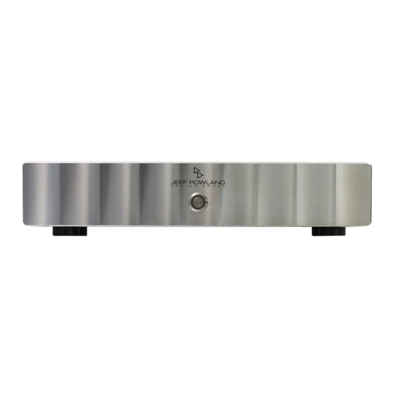
FRONT PANEL OPERATIONS Figure 1: Front Panel 1. FRONT PANEL POWER BUTTON Press this button to operate the amplifier. Press again to place the amplifier in Standby Mode. 2. POWER INDICATOR RING. This ring will illuminate white when the amplifier is operational. -
Page 12: Rear Panel Connections
6. LOUDSPEAKER MONO OUTPUT: Connect to Loudspeaker, 4 to 16 ohm impedance, for mono Operation. 7. STEREO/BRIDGED MODE SWITCH: Configures Model 535, as either a stereo or mono amplifier. When configured as a single mono amplifier, the overall gain of the amplifier is automatically adjusted to maintain the same gain as in stereo operation. - Page 13 AC MAINS INPUT CONNECTOR: Install an AC Power Cable, supplying 85 - 230 volt AC , into the AC mains input connector. FUSE HOLDER: Supplied with 6.3A 250V slow-blow or time-delay type fuse (MDL). Always replace with similar rating and type fuse. ! 1 3...
-
Page 14: Specification
SPECIFICATIONS 250 watts @ 8 ohms /500 watts @ 4 ohms, Output Power 100-230 Vac 900 watts @ 8 ohms, Mono, 230 Vac 700 watts @ 8 ohms, Mono, 100-120 Vac 5 Hz – 70 kHz, -3 dB Frequency Response 120 dB, A weighted Dynamic Range 55 microvolts, A weighted...


Need help?
Do you have a question about the 535 and is the answer not in the manual?
Questions and answers