Advertisement
Advertisement
Table of Contents

Related Manuals for JEFF ROWLAND Model 2


Summary of Contents for JEFF ROWLAND Model 2
- Page 1 JEFF ROWLAND...
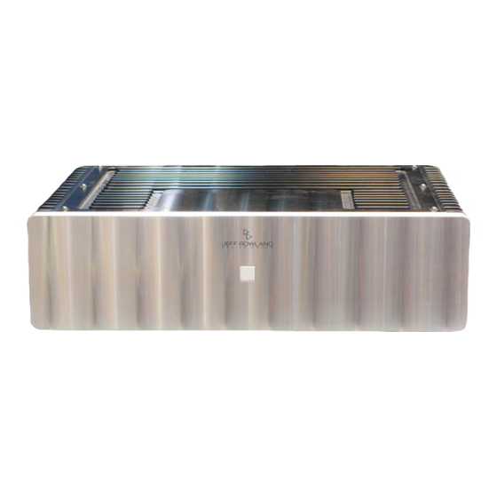
- Page 2 Model 2 Stereo Power Amplifier Owner’s Manual...
- Page 3 A thorough understanding of the operational features will allow you to gain the maximum performance and ease of use for which this Amplifier was designed. Please note that your Model 2 Stereo Amplifier serial number begins with the letter A.
-
Page 4: Product Features
Product Features XLR Balanced Input jacks for balanced (Differential Mode™) system configurations XLR to RCA Input adapters included User-selectable overall gain of 26 or 32 dB User-selectable input impedance of 36kΩ (HI) or 600Ω (LO) All internal signal circuitry is totally isolated from chassis and system ground potentials to eliminate noisy ground loops and to provide extreme immunity from RF interference Optional remote (wired or wireless power ON/OFF switching) - Page 5 Contents...
-
Page 6: Initial Inspection
We strongly suggest that you save all packing materials. If the Amplifier is returned to your dealer or Jeff Rowland Design Group, the original packing materials must be used for shipment. Neither Jeff Rowland Design Group nor the shipper can be held responsible for damages incurred during transit if the original factory packing is not used. - Page 7 Front & Rear Panel Function Controls...
- Page 8 Front & Rear Panel Function Controls Before attempting any system interconnection, please familiarize yourself with the front and rear panel controls of the Model 2 Amplifier. The descriptions below refer to the numbers associated with the features in the diagram above.
-
Page 9: Rear Panel Power Connections
Rear Panel Power Connections... -
Page 10: Installation
Amplifier as close as possible to its final installation point. Allow access to the rear panel for making connections. The Model 2 Amplifier is convection cooled, eliminating the need for fan or forced air cooling. When operating, the chassis should have at least two (2) inches of air space around the heatsink areas. -
Page 11: Signal Connections
Signal Connections... - Page 12 FRONT PANEL STANDBY/POWER button and lamp. An optional wired remote switch or infrared wireless remote sensor can be plugged into the REMOTE connector to facilitate this function. Contact your dealer or Jeff Rowland Design Group for further information and availability of this feature.
-
Page 13: Operation
Slight transients may be heard in the loudspeakers during the AC mains connect/disconnect transitions. Your new Model 2 Amplifier will require an initial break-in period of at least eighty (80) hours before maximum performance can be expected. Efficient break-in procedures require the Amplifier to be fully operational (playing music). -
Page 14: Performance Specifications
61 cm W x 50.8 cm D x 30.5 cm H 47 lbs. (21.5 kg) Weight 75 lbs. (34.0 kg) Shipping Weight Because Jeff Rowland Design Group is constantly analyzing new design improvements, we reserve the right to change or modify product specifications without notice or obligation. -
Page 15: Basic Troubleshooting
The Model 2 Amplifier can produce high power levels which, without well designed protection circuitry, could damage loudspeakers. Therefore, most fault conditions which may occur during use will be indicated by the Model 2 reverting to a standby condition. - Page 16 Condition FRONT PANEL STANDBY/POWER button illuminates normally but RIGHT, LEFT or both Amplifier CHANNELS do no operate or warm up to normal operating temperature. AC MAINS CIRCUIT BREAKER (rear panel) switches off or will not remain on. 50/60 Hz hum noise in loudspeakers. High frequency, random or scratching noise in loudspeakers.
- Page 17 Jeff Rowland Design Group Dealer. JEFF ROWLAND...
Need help?
Do you have a question about the Model 2 and is the answer not in the manual?
Questions and answers