Movon MDAS-9 Installation Manual Book
Hide thumbs
Also See for MDAS-9:
- User manual (16 pages) ,
- Installation manual book (57 pages) ,
- Quick install manual (7 pages)

Related Manuals for Movon MDAS-9


Summary of Contents for Movon MDAS-9
- Page 1 3950 NW 120 Ave, Coral Springs, FL 33065 TEL 561-955-9770 FAX 561-955-9760 MDAS-9 Installation Guidebook...
-
Page 2: Table Of Contents
CONTENTS General .......................... 6 Product .......................... 7 Specification........................7 Product components ......................8 Main Unit & Main Cable ....................9 Main Unit ........................9 2.3.1 Parts description ....................9 2.3.1.1 Mounting Frame and Back Cover ..............9 2.3.1.2 LED Description ....................10 2.3.1.3 Main Cable ........................ - Page 3 Reset MDAS-9 ........................29 PC and Android Phone Calibration ................32 Driver Setup (ONLY SUPPORTS WINDOWS OS)............32 Calibration Setup ......................32 Access MDAS-9 Calibration page via PC ............. 32 4.2.1 Select Vehicle Signal Types ..................33 4.2.2 You have 3 wiring options for installation; CAN-BUS / Analog wiring / GPS....33 Vehicle Data File (CAN-BUS) ................
- Page 4 How to Download CAN Data ..................47 Register in Vehicle Database ..................47 Download CAN Data file ....................47 Recognize MDAS-9 in computer .................. 49 Computer with Windows XP, 7, 8, 8.1 ................ 49 Computer with Windows 10 ..................49...
- Page 5 Version Date Contents Written Note 2.1.5 17.08.05 Initial Release John 2.1.6 17.08.08 Modified a picture (Power Cable, Smart John phone Calibration, PC Calibration) 2.1.7 17.08.09 Added FMS cable John 2.1.8 17.08.10 Added Recording Hours John 2.1.9 17.08.17 Modified product components John 2.2.0 17.09.14 Modified product accessory...
-
Page 6: General
1 General This MDAS installation requires custom wiring to various electronic signals in the vehicle. Please contact your local authorized installer to install. NAV-TV and Movon will hold no liability of any damage occurred during installation proceeded by users or unauthorized installers. -
Page 7: Product
2 Product Specification Cortex A7 Quad-Core Audio Out Speaker Front 1280 x 720 (HD) Camera Rear 1280 x 720 (HD) Input Range DC 10V ~ 36V Power Power 400mA @ 12V Max Consumption 3mA @ 12V Idle State Video MP4 (h.264 codec) Format Audio Storage... -
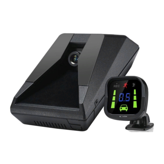
Page 8: Product Components
Product components Basic cables Main unit PCI Box Indicator (Power/CAN/Analog) Micro SD card (Consumable) Contactless CAN Rear Camera Video Out Cable Reader (Optional) (Optional) (Optional) (Optional) Micro 5PIN USB Wi-Fi Dongle Vibrator cable External Fuse (Optional for (Optional) (Optional for (Optional) installers) installers) -
Page 9: Main Unit & Main Cable
Main Unit & Main Cable 2.3.1 Main Unit 2.3.1.1 Parts description 2.3.1.2 Mounting Frame and Back Cover - 9 -... -
Page 10: Led Description
2.3.1.3 LED Description LED Status Illuminate Blink Illuminate Blink Blink Turn signal Initialization Firmware Working (L, R) Booting Calibration Update Before mode Mode booting 2.3.2 Main Cable Contactless CAN Reader - 10 -... -
Page 11: Indicator
Indicator Read user manual to see more description and functions. Indicator Error Table Camera Camera Indicator Connection Communicati View Block Communicati Visibility Error on Error Error on Error Indication Peripheral Component Interconnect Box (PCI Box) Peripheral Component Interconnect Box (PCI Box) is to connect the cables and accessories. -
Page 12: External Fuse (Optional)
Green In case of wiring constant power and ACC power External Fuse (Optional) MDAS-9 provides with an External Fuse to prevent from short circuiting the vehicle electrical system. Technical Cleaning Wipe (Optional) MDAS-9 provides Technical Cleaning Wipe for cleaning and removing dust, finger print on windshield. -
Page 13: Vibration Unit (Optional)
Vibration unit (Optional) * NOTE: Need Vibrator gender cable to use this and need to enable in Calibration. Read details in Chapter 4. Calibration 2.10 GPS (Optional) * Important, in case of use GPS for speed signal, warning timing can be inaccurate in decelerating circumstances. -
Page 14: Fms Cable (Optional)
2.12 FMS Cable (Optional) Transmit ADAS event data to Fleet Management System through RS-232 and CAN interfaces. * Caution: For FMS device connection, please connect RX, TX, and GND only. You can cut off the ACC/IGN. 2.13 FMS Converter (Optional) Convert ADAS event data received from RS-232 to CAN-Bus data to transmit. -
Page 15: Micro Sd Card (Consumable)
2.14 Micro SD Card (Consumable) * Micro SD card is consumable, only first 3 months will be guaranteed. It is recommended to format micro SD card regularly and replace it when it cannot be recognized in MDAS. ** Micro SD card speed shall be above Class 10 and it is recommended to use MLC type. -
Page 16: Micro 5 Pin Usb Cable (Optional For Calibration)
2.16 Micro 5 pin USB Cable (Optional for Calibration) * NOTE: You can use a common USB cable that supports data transmission. Use for Calibration procedures for Windows OS computers. Before use, please install RNDIS driver, first. (See Chapter 4.1) - 16 -... -
Page 17: Installation
② Connect vehicle signals (See Chapter 3.3 Wiring Combination) ③ Attach MDAS-9 (and indicator if needed) to the vehicle ④ Connect cables with MDAS-9 ⑤ Access MDAS-9 using Micro 5pin USB cable or Wi-Fi dongle ⑥ Calibration (See Chapter 4. Calibration procedure) ⑦ Test drive... -
Page 18: Wiring Combination And Description
Wiring Combination and Description 3.3.1 Main Cable * NOTE: Label color could be different due to production, please check label tags before wiring. 3.3.2 5Pin Analog Cable ***IMPORTANT *** Please do not leave any analog wires unattached. If there are any unused wires, please connect them to ground. -
Page 19: 4Pin Can Cable
3.3.3 4Pin CAN Cable Connection Description Color Label White CAN_H To CAN High wire Support CAN J1939 standard & CAN 2.0 (Support Version A, B) Green CAN_L To CAN Low wire 3.3.4 3Pin Power Cable Color Label Connection Description To ignition (ACC) power wire that turns off when key is at To ground source Black * Please ensure that is connected properly to ground,... - Page 20 3.3.5.1 Wiring with Contactless CAN Reader ① Connect Contactless CAN Reader to PCI box of MDAS-9. ② Remove double-sided tape ③ Attach the vehicle’s CAN wire as straight as possible to the double- sided tape by aligning with the hole marked in red.
-
Page 21: Wiring Combination
* After checking on operating of LED lights correctly, tie with a cable tie marked in yellow. *If CAN_H and CAN_L wires are attached correctly, LED lights illuminate bright. (If CAN_H and CAN_L wires are connected backwards, LED lights will be dim) 3.3.6 Wiring Combination * NOTE: See cable description table below. -
Page 22: Attach Mdas-9
*NOTE: It is very important to attach MDAS-9 at the center for the best performance. If MDAS-9 cannot be attached at the center, due to interior or space, attach MDAS-9 as close as possible to the center. - Page 23 ② Attach MDAS-9 to windshield. ③ Insert a small screw driver into small holes marked in red in the Main Unit Back Cover and press the bracket to separate. ④ Unscrew two cross recessed screws marked in red to remove the Upper Back Cover.
- Page 24 ⑤ Adjust the camera angle knob. (Refer to Chapter 4.2.6 to adjust the camera angle completely) *NOTE: Do not reassemble the Back Cover before completing Calibration procedure. *NOTE: In case of installing rear camera, refer to Chapter 3.6 - 24 -...
-
Page 25: Parts Connection
Parts connection 3.5.1 Indicator Connect Indicator using 4pin connector to Indicator port on PCI box. 3.5.2 Vibration module Connect Vibrator using 3pin connector to Vibrator port on PCI box. - 25 -... -
Page 26: Fms Cable
3.5.3 FMS Cable Use FMS cable and plug into FMS port on PCI box. 3.5.4 FMS Converter Use FMS Converter and plug into FMS port on PCI box. - 26 -... -
Page 27: Video-Out Cable
3.5.5 Video-Out Cable Use RCA cable and plug into Video OUT port on PCI box. This function does not provide other UI or graphics through via video-out. Screenshot - 27 -... -
Page 28: Connect Rear Camera To Mdas-9
Connect Rear Camera to MDAS-9 Following Chapter 3.4 in Attach MDAS-9 ① Unscrew two cross recessed bolt marked in red on top side. ② Push the two clips at the bottom side. ③ Remove PCB unit from mounting frame completely. -
Page 29: Reset Mdas-9
④ Connect Rear Camera Cable to connecter. Reset MDAS-9 If MDAS-9 has any malfunction, reboot the system or clear reset MDAS-9. * Caution: Once you clear reset MDAS-9, current settings such as CAN data or vehicle information will be removed ① Reboot (External) Press the Volume Down, Volume Up and Center Button at the same time. - Page 30 ② Reboot (Internal) Press the lower small button in red box. ③ Clear Reset (Internal) Press the upper small button in red box. - 30 -...
- Page 31 - 31 -...
-
Page 32: Pc And Android Phone Calibration
* For more details, see Chapter 6. Calibration Setup 4.2.1 Access MDAS-9 Calibration page via PC ① Connect MDAS-9 to PC using Micro USB cable with 5 pins. ② Start the engine. If you hear repeating beep sound, this means MDAS-9 is properly connected to computer. -
Page 33: Select Vehicle Signal Types
Please select proper calibration option below. 4.2.2.1 Vehicle Data File (CAN-BUS) For CAN-BUS connection, you have to choose “Vehicle info file” tab. MDAS-9 only recognizes encrypted CAN data from our Database site; http://info.mdas.co.kr (For further information, check Chapter 5: How to Download CAN data) * NOTE: MDAS-9 only reads a file named “mdasinfo.dat”. -
Page 34: Gps
Change polarity for turn signals and brake signal. Enter RPM correction value. 4.2.3 Vehicle Signal Check In this page, you can check whether MDAS-9 is receiving vehicle data properly. 4.2.3.1 Verify Speed Signal Start the engine and drive slowly in a safe place to see whether MDAS speed is corresponding with the vehicle’s speed. -
Page 35: Verify Turn Signal
“-“: Left Side / “+”:Right Side Center (If MDAS-9 is attached 5cm to the right from the center, input 5. If MDAS-9 is attached 5cm to the left from the center, input -5.) Distance from the camera to the center of the wheel. - Page 36 Camera Center Camera Height Vehicle Width Camera to bumper - 36 -...
-
Page 37: Camera Angle
4.2.5 Camera Angle Adjust the camera angle knob to locate the horizon between the red guide lines. In case of indoor installation or somewhere you cannot see the horizon properly, use same data to "Camera Height”. Mark the same height on the wall apart about 3 ~ 5 meters from the vehicle. -
Page 38: Hood Line
4.2.6 Hood Line Locate the red line at the end of the vehicle’s hood line to remove the useless area. 4.2.7 Rear Camera Setup For better angle of Rear Camera (DVR), adjust the camera module by rotating - 38 -... -
Page 39: Lane Departure Warning (Ldw) Sensitivity
4.2.8 Lane Departure Warning (LDW) Sensitivity You can adjust the LDW Sensitivity for your convenience. ① Enable LDW function. (On / Off) ② Set the Activation Speed (15, 30, 45, 60, 75km/h) ③ Set the sensitivity of LDW warning on a scale of 1 to 5. As the level gets higher, you will hear the warning sound earlier. -
Page 40: Safety Distance Alert Setup
④ Enable Sync with Brake (On / Off). If turning on this function, FCW alarm doesn’t alert while depressing the brake pedal once. ⑤ Warning sound: Select preferred warning sound for FCW 4.2.10 Safety distance alert setup ① Enable SDA function. (On / Off) ②... -
Page 41: Advanced Adas Setup
4.2.12 Advanced ADAS setup ① Enable Forward Proximity Warning function. (On / Off) ② Set the warning range on a scale of 1 to 3. As the level gets higher, you will hear the warning sound earlier. ③ Enable Front vehicle start alarm. (On / Off) 4.2.13 DVR (Dashcam) setup ①... -
Page 42: Fleet Management Setup
4.2.14 Fleet management setup ① Set Speed limit warning. (Off, 80, 90, 100, 110, 120, 140km/h) - You can set your own speed limit for your fleet. - You can set speed limit of your vehicle and get warning if you over the speed limit. -
Page 43: Mdas Setup Complete
A. Copy and paste vehicleprofile.dat into the micro SD card formatted by MDAS-9. B. Insert the micro SD card into MDAS-9 which you want to apply the exported profile. C. MDAS-9 will be rebooted automatically. Then, the profile will be applied to MDAS-9. -
Page 44: Setting Modification
Setting Modification Once MDAS-9 is calibrated well, you will see different menu when you access MDAS-9. 4.3.1 Menu Description ➢ System Update: You can update your firmware here. ➢ Default the System: You can reset and default current MDAS settings. -
Page 45: Update Firmware
② You are done when you see a pop-up message below. *NOTE: Do not touch or change anything while updating. Otherwise, MDAS-9 might lose its data and stop working. 4.3.3 Default MDAS Settings If you want to remove all data and return to a factory setting, click the “Default the System”... -
Page 46: Re-Calibration
4.3.4 Re-calibration If you click this menu, you will restart from 4.2.4.1 Vehicle Signal Check. 4.3.5 Change settings from warning setups If you click this menu, you will restart from 4.2.9 Lane Departure Warning (LDW) Sensitivity. If you only want to change settings about ADAS warnings, please press this. -
Page 47: How To Download Can Data
Register in Vehicle Database Open a web browser and enter http://info.mdas.co.kr/ You need to register and get an approval to log in. Please contact Movon Corp. or your local distributor for the approval. Download CAN Data file Once you log in, you will see Vehicle profile database page. - Page 48 Select Manufacturer, Model name and manufactured Year for the vehicle you need. You will see results on the right side of the page. If you find the right file for your vehicle, click “ ” icon to see and download the CAN data.
-
Page 49: Recognize Mdas-9 In Computer
6 Recognize MDAS-9 in computer * Please connect MDAS-9 to your laptop using Micro 5Pin USB cable before install the driver. * Computer with Windows XP, 7, 8, 8.1 Download RNDIS installer here: http://movon.co.kr/downloads/rndissetup.zip Please download and unzip it. When you install it, please click the right button on your mouse and select “Run as administrator”. - Page 50 ④ Click it using the right button of your mouse, then click “Properties”. ⑤ In the newly popped up window, Go to “Driver” tab, and click “Update Driver” - 50 -...
- Page 51 ⑥ Select “Browse my computer for driver software”. ⑦ Click “Browser…” button and “Browse For Folder” window will pop up. - 51 -...
- Page 52 ⑧ Choose “rndisdriver”. * Remember the path where you downloaded and unzipped the file * ⑨ Press “Next” on the page below. After installing the driver, you can close the windows. - 52 -...
- Page 53 ⑩ Open a web browser and type http://10.0.0.1 If you see MDAS-9 page like above, you have done everything perfectly. - 53 -...
Need help?
Do you have a question about the MDAS-9 and is the answer not in the manual?
Questions and answers