Table of Contents
Advertisement
This Instruction Book contains information for several models.
Read and keep this book for future reference.
This book contains important information on
SAFETY, ASSEMBLY, OPERATION, AND MAINTENANCE.
PRODUCT INFORMATION
The owner must be certain that all
the product information is included with the unit.
This information includes
the INSTRUCTION BOOKS,
the REPLACEMENT PARTS and the WARRANTIES.
This information must be included to make sure state laws
and other laws are followed.
RECORD THE FOLLOWING INFORMATION ABOUT YOUR UNIT.
THIS INFORMATION IS NECESSARY WHEN ORDERING PARTS
OR IN CASE OF LOSS OR THEFT.
F-050414L
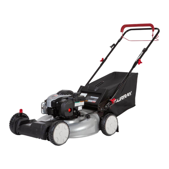
Models
22" Push
Advertisement
Table of Contents

Related Manuals for Murray 22


Summary of Contents for Murray 22
- Page 1 This information must be included to make sure state laws and other laws are followed. RECORD THE FOLLOWING INFORMATION ABOUT YOUR UNIT. THIS INFORMATION IS NECESSARY WHEN ORDERING PARTS OR IN CASE OF LOSS OR THEFT. F-050414L Models 22” Push...
- Page 2 MURRAY, INC. Two Year Limited Warranty Murray, Inc. warrants to the original purchaser that this unit shall be free from defects in ma- terial and workmanship under normal use and service for a period of Two (2) Years from the date of purchase; however, this warranty does not cover engines, accessories (such as snow blowers, snow blades, grass baggers and plows), transmissions, batteries and Nor- mal Wear Parts (except as noted below) or transaxles as the companies that manufacture these items furnish their own warranties and provide service through their authorized field...
-
Page 3: Owner's Information
OWNER’S INFORMATION This instruction book is written for a person with some mechanical ability. Like most service books, not all the steps are described. Steps on how to loosen or tighten fasteners are steps anyone can follow with some mechanical ability. Read and follow these instructions before you use the unit. Know your product: If you understand the unit and how the unit operates, you will get the best performance. - Page 4 Safe Operation Practices for Walk-Behind Mowers. This cutting machine is capable of amputating hands and feet and throwing objects. Failure to ob- serve the following safety instructions could result in serious injury or death. I. General Operation 1. Read, understand, and follow all instruc- tions on the machine and in the manual(s).
- Page 5 DO NOT: Do not mow near drop-offs, ditches, or em- bankments. The operator could lose footing or balance. Do not mow excessively steep slopes. Do not mow on wet grass. Reduced footing could cause slipping. III. Children Tragic accidents can occur if the operator is not alert to the presence of children.
-
Page 6: Safe Mowing Guide
Every person who uses power equipment must learn the difference between proper and improper use, safe and unsafe mowing prac- tices. Read the next few pages carefully. They can help you learn. Too often the mow- er user is inexperienced, not properly in- structed, or has not read the Instruction Book and instructions on the unit before using it for the first time. - Page 7 bruises, or even put out an eye. Often the per- son hurt by a thrown object is a bystander such as a child, another family member or a neigh- bor. Keep people and pets completely away from the mowing area. Direct the mower’s dis- charge away from areas where people can be.
- Page 8 Use only original equipment or approved sub- stitutions as service parts. If you need profes- sional service, select a shop that is an Authorized Service Center for your brand of mower. If you plan to service the unit yourself, follow directions in the Instruction Book. As you mow, remember children and pets are sometimes attracted to the activity.
- Page 9 While mowing, if you hit a foreign object, stop the engine. Remove the spark plug wire. Care- fully and thoroughly inspect the mower for damage. Make necessary repairs before re- starting. If the unit starts to vibrate abnormally, stop the engine immediately and check for the cause.
-
Page 10: After Mowing
BEFORE MOWING Be sure to dress correctly. Wear hard shoes, not sandals or tennis shoes. Examine the blade. A blade that is bent, cracked, or damaged must be replaced with a factory replacement blade. Fill the fuel tank outside. Clean off spilled fuel. Read and follow the Owner’s Manual, the instructions with the engine, and the instructions with any attachments. -
Page 11: Unpacking Instructions
WARNING: Before doing any assembly or maintenance to the mower, remove the wire from the spark plug. NOTE: In this instruction book, left and right describe the location of a part with the operator standing behind the handle. UNPACKING INSTRUCTIONS The mower was fully assembled at the factory. - Page 12 HOW TO ADJUST THE HANDLE HEIGHT The handle bracket has two assembly posi- tions. A HIGH and a LOW position (Figure 4). The HIGH position will raise the handle ap- proximately four inches. HIGH Ç Ç Ç Ç 1. Remove the wingnuts and bolts from the right and left handle brackets (Figure 5).
-
Page 13: How To Prepare The Engine
HOW TO PREPARE THE ENGINE ENGINE DOES NOT CONTAIN OIL OR GASOLINE Fill the engine with the proper amount of oil. See the engine manufacturer’s instructions for the type of gasoline and oil to use. Before you use the unit, read the information on safety, op- eration, maintenance, and storage. -
Page 14: Engine Stop Lever
ENGINE STOP LEVER Release the engine stop lever and the engine and the blade will automatically stop. To run the engine, hold the engine stop lever in the Operating position (Figure 8). Before you start the engine, operate the en- gine stop lever several times. -
Page 15: Engine Maintenance
ENGINE MAINTENANCE Use the following maintenance section to keep your unit in good operating condition. All the maintenance information for the engine is in the “Engine Instruction Book”. Before you start the engine, read this book. WARNING: Before you make an inspection, adjustment (except carburetor), or repair, stop the engine and disconnect the wire... -
Page 16: Blade Service
BLADE SERVICE WARNING: Before you inspect the blade or the blade adapter, disconnect the wire to the spark plug. If the blade hits an object, stop the engine. Disconnect the wire to the spark plug. Check the unit for damage. Frequently check the blade for wear or dam- age such as cracks. -
Page 17: For Storage
5. Make sure the blade is balanced. Use a screwdriver and hold the blade parallel to the ground as shown. A blade that is bal- anced will stay parallel to the ground. If the blade is not balanced, the heavy end will rotate toward the ground. -
Page 18: Troubleshooting Chart
TROUBLE SHOOTING CHART The Engine will not start. 1. Make sure the fuel tank is filled with clean gasoline. Do not use old gasoline. 2. On a cold engine, push the primer button (optional on some models). For the number of times required to push the primer button, see the engine manufacturer’s instructions. - Page 19 F-050414L...
- Page 20 HANDLE - BRIGGS & STRATTON MODELS DESCRIPTION Handle, Upper (Black) Handle, Upper (Gray) Handle, Lower (Black) Handle, Lower (Gray) Bolt Knob, Plastic Used on Briggs & Stratton Classic, Sprint, Quattro, Q-Style and QS-Style engines. # Used on Briggs & Stratton Quantum engines. F-050414L PART NO.
- Page 21 DESCRIPTION Handle, Upper (Black) Handle, Upper (Gray) Handle, Lower (Black) Handle, Lower (Gray) Lever, Stop Knob, Plastic F-050414L PART NO. 1101556E701 1101556E724 071137E701 071137E724 1101964E700 071294 DESCRIPTION Engine Stop Cable Guide, Rope Locknut Bolt Fastener, Cable PART NO. 1102041 071530 15x116 002x77 1101353...
- Page 22 MODELS WITH STANDARD WHEELS F-050414L...
- Page 23 MODELS WITH STANDARD WHEELS Engine ‡ Housing Height Adjuster, Left Rear (8” Wheels) Height Adjuster, Left Rear (7” Wheels) Knob Wheel and Tire # Locknut, Flange Bolt, Carriage Bolt, Engine Height Adjuster, Left Front (8” Wheels) Height Adjuster, Left Front (7” Wheels) Washer, Belleville Washer Bolt, Hex...
-
Page 24: Wheels And Tires
Look at the illustrations. Select the wheel and the tire you want and order from the following chart. WHEEL SIZE & TYPE 6-inch Plastic, White 6-inch Plastic, Gray 7-inch Plastic, White 7-inch Plastic, Gray 8-inch Plastic, White 8-inch Plastic, Gray 8-inch Ball Bearing, Gray 12-inch, Gray F-050414L... - Page 25 F-050414L...
- Page 26 F-050414L...
- Page 27 F-050414L...
-
Page 28: How To Order Repair Parts
BROWN & WISER, INC. 9991 S.W. Avery Street Tualatin, OR 97062 (503)692−0330 1−800−882−4782 FAX (503)691−2041 Alaska, Idaho (counties Ada, Adams, Benewah, Boise, Bonner, Boundry, Canyon, Clearwater, Elmore, Gem, Idaho, Kooten, Latah, Lewis, NEZ Perce, Owyee, Payette, Ravalli, Shoshone, Valley, Washington), Montana (counties...
Need help?
Do you have a question about the 22 and is the answer not in the manual?
Questions and answers
Self propelled drive stopped working. How can I fix it?
To fix the self-propelled drive on a Murray 22 mower, follow these steps:
1. Check the Drive Cable: Inspect the cable that lifts the drive mechanism. If it is stretched or damaged, it may not engage the drive. A temporary fix is to tighten the cable, such as tying a knot, but replacing it is more reliable.
2. Inspect the Belt: Remove the belt cover and check the condition of the drive belt. Even if it's not visibly cracked or shredded, it may be worn or slipping.
3. Test the Drive Mechanism: Lift the rear wheels off the ground and manually raise the drive mechanism. If the wheels turn with the flywheel and cannot be turned backwards, the mechanism is likely working. If not, it may need further inspection or replacement.
4. Check for Obstructions or Damage: Make sure there are no obstructions or damage to the drive gears or wheel assemblies that could prevent movement.
If these steps do not restore function, replacing the cable or belt may be necessary.
This answer is automatically generated
OK On the front of my Murray 22 push mower front wheel drive. How do i open front part where pully is located or where is the front belt tension bolt
To access the pulley area or locate the front belt tension bolt on a Murray 22" push mower:
1. Loosen the belt tension bolt.
2. Remove the front of the drive belt from the transmission pulley.
3. Slip the rear of the drive belt over the end of the blade.
4. If needed, refer to Figure 25 in the manual for the exact location of the belt tension bolt.
After maintenance, reassemble the drive belt by reversing these steps and set the belt tension correctly.
This answer is automatically generated
How do i change the drive belt on front wheel driven Murray push mower?
To change the drive belt on a front-wheel-driven Murray push mower model 22, follow these steps:
1. Loosen the belt tension bolt.
2. Remove the front of the drive belt from the transmission pulley.
3. Slip the rear of the drive belt over the end of the blade to remove it.
4. Replace the belt with a factory-approved replacement belt.
5. Reassemble by reversing the removal steps.
6. Set the belt tension:
a. Tighten the adjuster nut until it touches the spacer.
b. Loosen the adjuster nut slightly until the spacer can turn.
7. Install the belt cover.
8. Test the drive system to ensure it disengages correctly. If it does not, take the mower to an authorized service center before use.
This answer is automatically generated
How do you remove the cover off the self propelled section so I can check the belt?
Self propelled drive stopped working...only used it once. How can I fix it ?
Is there a video available to assist me in replacing drive belt of a Murray 22