Beijer Electronics BFI-E3 Series Startup Manual
Hide thumbs
Also See for BFI-E3 Series:
- Start-up (28 pages) ,
- Quick start manual (41 pages) ,
- Quick start manual (37 pages)
Table of Contents
Advertisement
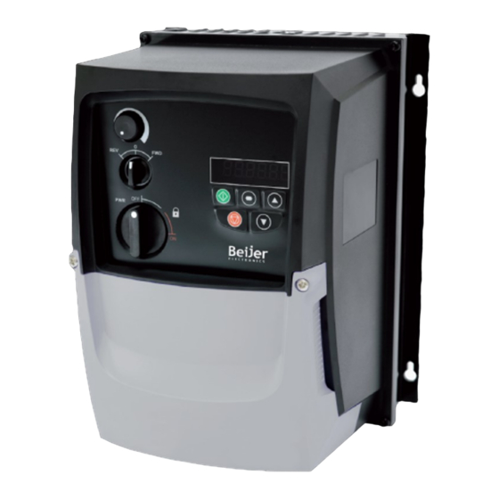
Beijer Electronics Frequency Inverter BFI-E3
1 Start-up document
This document is a simple start-up guide describing basic functionality of the drive BFI-
E3, firmware 3.08. Detailed explanations are to be read in User Manual BFI-E3 and is
attached with the drive itself. but also possible to download from
beijerelectronics.se
2 Important Safety Information
Read IMPORTANT SAFETY INFORMATION below, especially Warnings and Caution.
Danger : Indicates a risk of electric shock, which, if not
avoided, could result in damage to the equipment and
possible injury or death.
This variable speed drive product is intended for professional incorporation into complete equipment or systems as part of a fixed installation. If installed
incorrectly it may present a safety hazard. The BFI uses high voltages and currents, carries a high level of stored electrical energy, and is used to control
mechanical plant that may cause injury. Close attention is required to system design and electrical installation to avoid hazards in either normal operation
or in the event of equipment malfunction. Only qualified electricians are allowed to install and maintain this product.
System design, installation, commissioning and maintenance must be carried out only by personnel who have the necessary training and experience.
They must carefully read this safety information and the instructions in this Guide and follow all information regarding transport, storage, installation and
use of the BFI, including the specified environmental limitations.
Do not perform any flash test or voltage withstand test on the BFI. Any electrical measurements required should be carried out with BFI disconnected.
Electric shock hazard! Disconnect and ISOLATE the BFI before attempting any work on it. High voltages are present at the terminals and within the
drive for up to 10 minutes after disconnection of the electrical supply. Always ensure by using a suitable multimeter that no voltage is present on any
drive power terminals prior to commencing any work.
Where supply to the drive is through a plug and socket connector, do not disconnect until 10 minutes have elapsed after turning off the supply.
Ensure correct earthing connections. The earth cable must be sufficient to carry the maximum supply fault current which normally will be limited by the
fuses or MCB. Suitably rated fuses or MCB should be fitted in the mains supply to the drive, according to any local legislation or codes.
Do not carry out any work on the drive control cables whilst power is applied to the drive or to the external control circuits.
Within the European Union, all machinery in which this product is used must comply with Directive 98/37/EC, Safety of Machinery. In particular, the
machine manufacturer is responsible for providing a main switch and ensuring the electrical equipment complies with EN60204-1.
The level of integrity offered by the BFI control input functions – for example stop/start, forward/reverse and maximum speed is not sufficient for use in
safety-critical applications without independent channels of protection. All applications where malfunction could cause injury or loss of life must be
subject to a risk assessment and further protection provided where needed.
The driven motor can start at power up if the enable input signal is present.
The STOP function does not remove potentially lethal high voltages. ISOLATE the drive and wait 10 minutes before starting any work on it. Never carry
out any work on the Drive, Motor or Motor cable whilst the input power is still applied.
The BFI can be programmed to operate the driven motor at speeds above or below the speed achieved when connecting the motor directly to the mains
supply. Obtain confirmation from the manufacturers of the motor and the driven machine about suitability for operation over the intended speed range
prior to machine start up.
Do not activate the automatic fault reset function on any systems whereby this may cause a potentially dangerous situation.
The BFI has an Ingress Protection rating of IP20 or IP66 depending on the model. IP20 units must be installed in a suitable enclosure.
When mounting the drive, ensure that sufficient cooling is provided. Do not carry out drilling operations with the drive in place, dust and swarf from
drilling may lead to damage. BFI are intended for indoor use only.
The entry of conductive or flammable foreign bodies should be prevented. Flammable material should not be placed close to the drive
Relative humidity must be less than 95% (non-condensing).
Ensure that the supply voltage, frequency and no. of phases (1 or 3 phase) correspond to the rating of the BFI as delivered.
Never connect the mains power supply to the Output terminals U, V, W.
Do not install any type of automatic switchgear between the drive and the motor
Wherever control cabling is close to power cabling, maintain a minimum separation of 100 mm and arrange crossings at 90 degrees
Ensure that all terminals are tightened to the appropriate torque setting
Do not attempt to carry out any repair of the BFI. In the case of suspected fault or malfunction, contact your local Beijer Electronics office for further
assistance.
Beijer Electronics a company in the Beijer Electronics Group
Parent Company (Reg. office)
Beijer Electronics AB
P.O. Box 426
SE-201 24 MALMÖ, SWEDEN
Telephone +46 40 35 86 00
Fax +46 40 93 23 01
Visiting address: Stora Varvsgatan 13a, Malmö
or
.no
or
.dk
or
.de
or
.com
www.
or
.com
.tr/
or
.tw
or
.co.uk/
Danger : Indicates a potentially hazardous
situation other than electrical, which if not
avoided, could result in damage to property.
Subsidiaries
Norway, Drammen: Beijer Electronics AS, +47 32 24 30 00
Denmark, Copenhagen: Beijer Electronics A/S,
Germany, Nürtingen: Beijer Electronics GmbH, +49 7022 9660 0
UK, Castle Donington: Beijer Electronics Products, +44 (0)845519 5430
France, Champlan: Beijer Electronics +33 (0)1 69 10 22 42
Turkey Istanbul: Beijer Electronics ve Ticaret A.s 0090 216 366 32 0200
KI00369B 2019-09
Sida 1 (24)
+45 75 76 66
Advertisement
Table of Contents

Related Manuals for Beijer Electronics BFI-E3 Series


Summary of Contents for Beijer Electronics BFI-E3 Series
-
Page 1: Start-Up Document
Wherever control cabling is close to power cabling, maintain a minimum separation of 100 mm and arrange crossings at 90 degrees Ensure that all terminals are tightened to the appropriate torque setting Do not attempt to carry out any repair of the BFI. In the case of suspected fault or malfunction, contact your local Beijer Electronics office for further assistance. -
Page 2: Table Of Contents
The material may only be used with products or software supplied by Beijer Electronics. Beijer Electronics assumes no responsibility for any defects in the material, or for any consequences that might arise from the use of the material. -
Page 3: Installation
Beijer Electronics Frequency Inverter BFI-E3 KI00369B 2019-09 4 Installation The drive should be mounted in a vertical position only on a flat, flame resistant vibration free mounting using the integral holes. IP66 is allowed for outdoor mounting. But it is recommended having an external roof to avoid snow directly on drive. -
Page 4: Physical Dimensions Ip66
Beijer Electronics Frequency Inverter BFI-E3 KI00369B 2019-09 Physical dimensions IP66 BFI-E3- -IP66 Drive Weight size [mm] Height Depth Width 1 x 230 V 3x380-480 V [mm] [mm] [mm] [mm] [mm] [kg] [mm] [mm] [mm] 0023-0070 0022-0041 25.0 [0,37-1,5 kW] [0,75-1,5 kW]... -
Page 5: Fuses, Cable Dimensions And Power Loses
Beijer Electronics Frequency Inverter BFI-E3 KI00369B 2019-09 Fuses, cable dimensions and power loses 200-240V ±10% - Single Phase Input – 3 Phase Output Output BFI-E3 Nominal Fuse or Supply Supply Nominal Motor Max Motor Power Power [kW] model Input Cable Size,... -
Page 6: Installation Of Power Supply, Grounding And Motor Cable
Beijer Electronics Frequency Inverter BFI-E3 KI00369B 2019-09 Installation of power supply, grounding and motor cable L1/N L2/N Drive is to be connected with ground/PE by separate grounding wire. 1-phase power supply should be connected to L1/L, L2/N. 3-phase power supply should be connected to L1, L2 and L3. -
Page 7: Brake Transistor And External Brake Resistor
Beijer Electronics Frequency Inverter BFI-E3 KI00369B 2019-09 Brake transistor and external brake resistor If a larger amount of regenerate power is being produced than the BFI can handle at stop function AC Flux Braking can be used. Means that motor is being over excitated during stop and used as brake resistor. -
Page 8: Overview Control Inputs/Outputs
Beijer Electronics Frequency Inverter BFI-E3 KI00369B 2019-09 Overview control inputs/outputs Picture below shows an overview of control signals for the drive and factory set functionality when the internal 24 VDC of the BFI is being used. +24 VDC 0-10 V output,... -
Page 9: Basic Parameter Setting
Beijer Electronics Frequency Inverter BFI-E3 KI00369B 2019-09 5 Basic Parameter setting The basic parameter setting that always is to be checked or modified is listed below: Para- Name Default To be set Function meter settng Maximum Frequency P-01 50 Hz If P-10, Motor rated speed, ≠... -
Page 10: Digital Start In 2 Directions And Analog Frequency Set Point
Beijer Electronics Frequency Inverter BFI-E3 KI00369B 2019-09 Digital start in 2 directions and analog frequency set point Start of drive is done by either Start- and Direction signals or Start Forward/Start Reverse. Third digital input decides whether Preset speed1, P-20 or analog input is valid. If 4-20 mA is to be used current must flow into terminal 6 and out on terminal 7. -
Page 11: Digital Start Signal And Frequency Set Point By Led Display
Beijer Electronics Frequency Inverter BFI-E3 KI00369B 2019-09 Digital start signal and frequency set point by LED display Connect terminal 2 with terminal 1 to give digital start signal forward and terminal 3 to 1 for digital start signal reverse. Output frequency can be increased and decreased by push button ”Up” and ”Down”. In parameter P-31 the start speed can be decided either latest speed or minimum speed. -
Page 12: Analog Output, 0-10 Vdc
Beijer Electronics Frequency Inverter BFI-E3 KI00369B 2019-09 Analog output, 0-10 VDC Between terminal 8 and 9 an analog output of 0-10 VDC is generated. Maximum load is 20 mA. 0-10 V Output Para- Name Default Function meter setting 0 V reference 8: Output Frequency: 0 to 100% = 0-10 V =>... -
Page 13: Vector Control With Standard Induction Motor
Beijer Electronics Frequency Inverter BFI-E3 KI00369B 2019-09 5.11 Vector control with standard induction motor Vector control is a built in function that gives additional torque at low speed and also makes motor speed constant even though load of the motor fluctuates. -
Page 14: Modbus Rtu
Beijer Electronics Frequency Inverter BFI-E3 KI00369B 2019-09 5.14 Modbus RTU A Modbus RTU network with BFI-E3, BFI-H3 or BFI-P2 is connected as below: Modbus master X2 panel IP20 IP20 RS485 + Pin1 CAB 113 OPT-2- RS485 – Pin6 J45SP-BFI Pin5... -
Page 15: Canopen
Beijer Electronics Frequency Inverter BFI-E3 KI00369B 2019-09 5.15 CANopen BFI-E3 should have firmware version 3.08 (from August 2019) for full functionality. Eds-file to be used for BFI-E3 is called BFI-E3.eds and is to be downloaded from www.beijerelectronics. A CANopen network with BFI-E3 IP20 are connected as below. -
Page 16: Pi-Control
Beijer Electronics Frequency Inverter BFI-E3 KI00369B 2019-09 5.16 PI-control +24 VDC DI1: Start signal Status Action DI2: PI / Pre Speed 1 P12=5 & P15 = 0 DI1 DI2 any No output from drive 0-10V / 4-20mA PI-feedback Run with PI-control... -
Page 17: Spin Start
Beijer Electronics Frequency Inverter BFI-E3 KI00369B 2019-09 5.18 Spin start On start the drive will attempt to determine motor speed and control the motor from its current speed. This gives a few seconds of start delay. Very useful in fan applications. -
Page 18: Keypad
Beijer Electronics Frequency Inverter BFI-E3 KI00369B 2019-09 6 Keypad The drive is configured and its operation monitored via the keypad and display. Used to display real-time information, to access and exit NAVIGATE parameter edit mode and to store parameter changes... -
Page 19: Monitoring From Keypad
Beijer Electronics Frequency Inverter BFI-E3 KI00369B 2019-09 Monitoring from Keypad Put P14=201 to access monitor values in parameter group P0. Description Display range Explanation P0-01 1st Analog Input Value 0 … 100% 100% = max input voltage P0-02 2nd Analog Input Value 0 …... -
Page 20: Ip66, Main Switch Start Stop Switch And Potentiometer
Beijer Electronics Frequency Inverter BFI-E3 KI00369B 2019-09 IP66, Main switch, start/stop switch and potentiometer By adjusting the parameter settings the drive can be configured for multiple applications and not just for Forward or Reverse. This could typically be for Hand/Off/Auto applications (also known and Local/Remote) for HVAC and pumping industries. -
Page 21: Specification
Beijer Electronics Frequency Inverter BFI-E3 KI00369B 2019-09 Specification BFI-E3 (1 x 230 V) BFI-E3 (3 x 400 V) Drive Model 041 058 095 Output power, kW 0,37 0,75 0,75 Output current A, 10,5 15,3 Overload rating, A 175 % av märkström i 2,0 sek; 150 % i 1 min Output voltage 3-fas, 0 V upp till ansluten nätspänning... -
Page 22: Warning And Alarm Codes
Beijer Electronics Frequency Inverter BFI-E3 KI00369B 2019-09 8 Warning and Alarm codes Drive Display Fault Description Corrective Action Fault Code Number Drive is healthy and in stop condition. Motor is not energized. No enable signal is present to start drive... - Page 23 Beijer Electronics Frequency Inverter BFI-E3 KI00369B 2019-09 AtF-01 Auto tune Fault The motor parameters measured through the auto tune are not correct. AtF-02 Check the motor cable and connections for continuity. Check all three phases of the motor are present and balanced.
-
Page 24: Beijer Electronics Frequency Inverter Bfi-E3 Ki00369B
Beijer Electronics Frequency Inverter BFI-E3 KI00369B 2019-09 24 (24) www.beijer.se www.beijer.no www.beijer.dk www.beijerelectronics.de www.beijerelectronics.com www.beijerelektronik.com.tr...
Need help?
Do you have a question about the BFI-E3 Series and is the answer not in the manual?
Questions and answers