Advertisement
Quick Links
Advertisement

Summary of Contents for Rutenbeck NV 2 TC
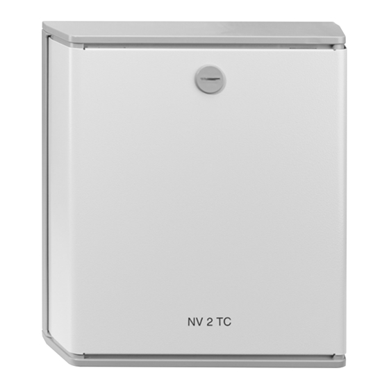
- Page 1 NV 2 TC Installation instructions...
- Page 2 Connection Hints Installation Installation of the accumu- lators The NV 2 TC has to be instal- To open the NV 2 TC, unlock Plug the flat receptacles with led in dry rooms with tempera- the cover, hold the cover with correct polarity (red on plus) tures between -5°C to 45°C.
-
Page 3: Technical Data
Function Technical Data Power supply The NV 2 TC keeps the Te- lecontrol devices TC, TC EIB Voltage 230 V (+ 6 %, - 10 %) 50 Hz and TC Alarm as well as the Power consumption max. 35 VA... - Page 4 Figure 1 Opening and closing of the cover Figure 2 Wall mounting...
- Page 5 NA with an alarm input M of the TC, if necessary fuse 2 2.5 A T - + NA fuse 3 2.5 A T NV 2 TC L1 N PE 230 V fuse 2 2.5 A T Figure 3 Connection diagram...
- Page 6 Discharge Behavior The following table shows the discharge behavior of the NV 2 TC with different load. Status Current in mA Time in Hours TC idle TC on subscriber line TC idle + 1 output (50 mA) TC idle + 2 outputs (50 mA each)
-
Page 7: Manufacturer's Declaration
Guaranty Manufacturer’s Declaration Warranty We guarantee the perfect We, Wilhelm Rutenbeck function of the NV 2 TC for 2 GmbH & Co. KG, declare on years after date of purchase our sole responsibility, that the (receipt) providing that it was... - Page 8 Niederworth 1-10 58579 Schalksmühle Phone +49 2355 82-0 +49 2355 82-105 Germany www.rutenbeck.de mail@rutenbeck.de...

Need help?
Do you have a question about the NV 2 TC and is the answer not in the manual?
Questions and answers