Table of Contents
Advertisement
Quick Links
I
A Spanish language version of these instructions is available by contacting the
manufacturer listed on the rating plate.
La version espanola de estas instruccions se puede obtener al escribirle a la fábrica
cuyo nombre aparece in la placa de especificaciones.
INSTALLATION/OPERATING MANUAL
WITH PARTS LISTING AND TROUBLESHOOTING GUIDE
WARNING
To avoid damage or injury, there
must be no materials stored
against the indirect water heater
and proper care shall be taken to
avoid unnecessary contact
(especially by children) with the
indirect water heater.
Do not store or use
gasoline or other
flammable liquids in
the vicinity of this
water heater or any
other appliance.
For your family's comfort, safety, and convenience, we
recommend this water heater be installed and serviced by
a plumbing professional.
D
OUBLE
NDIRECT
WATER HEATER
-
WALL
-
FIRED
238-45085-00F REV 5/18
Advertisement
Table of Contents

Related Manuals for Bradford White DW265L


Summary of Contents for Bradford White DW265L
- Page 1 OUBLE WALL NDIRECT FIRED WATER HEATER A Spanish language version of these instructions is available by contacting the manufacturer listed on the rating plate. La version espanola de estas instruccions se puede obtener al escribirle a la fábrica cuyo nombre aparece in la placa de especificaciones. INSTALLATION/OPERATING MANUAL WITH PARTS LISTING AND TROUBLESHOOTING GUIDE WARNING...
- Page 2 CONGRATULATIONS! You have just purchased one of the finest water heaters on the market today! This installation, operation, and instruction manual will explain in detail the installation and maintenance of your new Indirect water heater. We strongly recommend that you contact a plumbing professional for the installation of this water heater.
-
Page 3: Table Of Contents
CAUTION The maximum boiler water supply temperature to the indirect heat exchanger must not exceed 240°F (115°C). NOTICE Insulation blankets are not required for this water heater. This water heater meets or exceeds the ASHRAE/IES 90.1b standards with respect to insulation and standby loss requirements. TABLE OF CONTENTS I- IMPORTANT INFORMATION…………….…... -
Page 4: I- Important Information
SECTION I IMPORTANT INFORMATION -READ CAREFULLY- The equipment must be installed in accordance with those installation regulations required in the area where the installation is to be made. These regulations must be carefully followed in all cases. Authorities having jurisdiction shall be consulted before installations are made. - Page 5 Important Info continued- DANGER DO NOT store or use gasoline or other flammable, combustible, or corrosive vapors and/or liquids in the vicinity of this or any other appliance. IF YOU SMELL GAS: DO NOT try to light any appliance. DO NOT touch any electric switch;...
- Page 6 Important Info continued- WARNING Installation is not complete unless a properly sized/capacity pressure and temperature relief valve is installed into the side of the water heater. See the General Information section of this manual for details. This water heater contains very hot water under high pressure. Do not unscrew any pipe fittings or attempt to disconnect any components of this water heater without positively assuring the water is cool and has no pressure.
- Page 7 Important Info continued- WARNING It is the responsibility of the installing contractor to see that all controls are correctly installed and are operating properly when the installation is complete. DO NOT operate the water heater with jumpered or absent controls or safety devices. DO NOT tamper with or alter the water heater and/or controls.
-
Page 8: Ii- Specifications
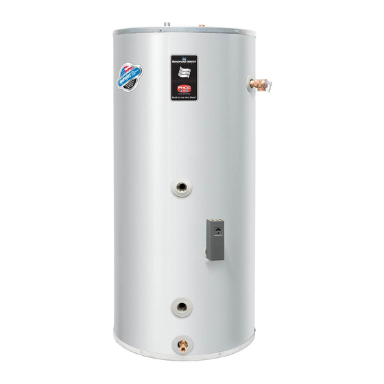
SECTION II SPECIFICATIONS ANODES COLD WATER OUTLET 3/4” NPT HOT WATER OUTLET 3/4” NPT WIRING JUNCTION BOX TEMPERATURE AND PRESSURE RELIEF VALVE FROM BOILER SUPPLY 3/4” NPT THERMOSTAT UNDER COVER TO BOILER RETURN 3/4” NPT DRAIN COUPLING- 3/4” NPT DRAIN VALVE – 5/8” NH Figure 1 –... - Page 9 Specifications continued- Table 2: Water Heater Capacities Tank Coil MODEL Capacity Volume Weight Weight (Gal) (Gal) (Lbs) (Lbs) 40-Gal. 50-Gal. 65-Gal. 80-Gal. Table 3: AHRI Certified Water Heater Ratings Continuous Standby Minimum Minimum First Hour Draw Heat Loss Output of Heat Source MODEL Rating...
- Page 10 Specifications continued- Table 5: Water Heater Performance Pressure Drop at Hot Water Coil Heat Rated Heat MODEL Availability Transfer Area Source Flow Rate (Minutes) (Sq Ft) (Feet of Head) 40-Gal. 14.2 50-Gal. 14.2 65-Gal. 10.8 14.2 80-Gal. 13.5 14.2 NOTICE If the boiler takes longer to heat up from a cold start than the water availability as noted above, hot water shortage may occur.
-
Page 11: Iii- General Information
SECTION III GENERAL INFORMATION FEATURES This water heater contains the following features: HEAT EXCHANGER -- The heat exchanger (coil) has 3/4” NPT female fittings. Water heaters with a double-wall heat exchanger meet the Uniform Plumbing Code for installation in all potable water systems. The double- wall construction provides protection in the event that either the potable or hydronic heat exchanger barrier is penetrated. - Page 12 General Info continued- TEMPERATURE AND PRESSURE RELIEF VALVE WARNING Keep clear of the combination temperature and pressure relief valve discharge line outlet. The discharge may be hot enough to cause scald injury. The water is under pressure and may splash. For protection against excessive temperatures and pressure, install temperature and pressure protective equipment required by local codes, but not less than a combination temperature and pressure...
- Page 13 General Info continued- WARNING Install a discharge line so that water discharged from the temperature and pressure relief valve will exit within six (6) inches above, or any distance below, the structural floor and cannot contact any live electrical part. The discharge line is to be installed to allow for complete drainage of both the temperature and pressure relief valve and the discharge line.
-
Page 14: Iv- Pre Installation
SECTION IV PRE-INSTALLATION UNPACKING INSPECT SHIPMENT carefully for any signs of damage. If damage is noted, do not install the product. Contact the shipper or manufacturer. All equipment is carefully manufactured, inspected, and packed. Our responsibility ceases upon delivery of the packaged water heater to the carrier in good condition. - Page 15 Pre-installation continued- NOTICE Increasing the boiler DOE heating capacity above the values listed in Table 3 will not increase the rating of the water heater. 2. Circulator Sizing – Refer to Table 5 for the corresponding pressure drop through the coil for the given model. Calculate the pressure drop of all straight pipe and fittings on the supply and return of the water heater at the selected flow rate.
- Page 16 Pre-installation continued- DOMESTIC HOT WATER PRIORITY Two options are available, Priority and Non-Priority. 1. Priority – Demand for space heating is interrupted or postponed until the domestic hot water demand is satisfied. This option provides maximum delivery of domestic hot water.
- Page 17 Pre-installation continued- Clearance from Combustible Materials Sides Front Rear 0” 0” 0” 0” Table 6 – Combustible Material Clearances Recommended Service Clearances Non-Piping Front T & P Relief Side (Thermostat) Rear Valve Side 4” 16” 0” 4” Table 7 – Service Clearances CAUTION Do not drop water heater.
-
Page 18: V- Water Connections
Pre-installation continued- MOVE THE WATER HEATER TO A PERMANENT POSITION BY SLIDING OR WALKING. NOTICE For California installation this water heater must be braced, anchored, or strapped to avoid falling or moving during an earthquake. See instructions for correct installation procedures. Instructions may be obtained from California Office of the State Architect, 400 P Street, Sacramento, CA 95814. - Page 19 Water Connections continued- CAUTION If sweat fittings are to be used, DO NOT apply heat to the nipples on top of the water heater. Sweat the tubing to the adapter before fitting the adapter to the water connections. It is imperative that heat is not applied to the nipples containing a plastic liner.
- Page 20 Water Connections continued plumbing inspector should be contacted on how to control this situation. 3. After installation of the water lines, open the main water supply valve and fill the water heater. While the water heater is filling, open several hot water faucets to allow air to escape from the water system.
- Page 21 Water Connections continued- Figure 2 - Water Boiler Piping with Zone Valves 2. For a space heating system that utilizes CIRCULATORS, refer to Figure 3. The indirect-fired water heater connection labeled “FROM BOILER SUPPLY” should be piped to the boiler supply piping.
- Page 22 Water Connections continued- CONNECT STEAM BOILER SUPPLY PIPING Figure 4 represents a typical steam boiler connection diagram. Refer to the boiler installation manual or contact the boiler manufacturer for an appropriate piping diagram. The use of a union, shut-off valves, and a drain valve is recommended for future service convenience.
-
Page 23: Vi- Electrical Connections
SECTION VI ELECTRICAL CONNECTIONS Install electric wiring in accordance with National Electric Code or the Canadian Electrical Code and local regulations. See the boiler’s installation manual for wiring diagrams. DANGER Positively assure all electrical connections are unpowered before attempting installation or service of electrical components or connections of the water heater or building. - Page 24 Electrical Connections continued- The thermostat switch is a single pole, single throw device. The field connections shall be used as a control for one leg of the electrical circuit. The thermostat switch can be used in the range of 24 to 480 volts with a maximum current load of 15 amps. Any and all wiring shall be sized and installed to satisfy the voltage and amperage used.
- Page 25 Electrical Connections continued- If a zone valve to used to control the heating fluid flow from the boiler to the water heater, a zone step-down transformer is required between the water heater thermostat and the zone valve. Connect the white wire on the water heater to one leg of the transformer primary side.
-
Page 26: Vii- Operating Instructions
SECTION VII OPERATING INSTRUCTIONS WARNING Water heaters are heat-producing appliances. To avoid damage or injury there must be no materials stored against the water heater, and proper care must be taken to avoid unnecessary contact (especially by children) with the water heater. UNDER NO CIRCUMSTANCES SHALL FLAMMABLE MATERIALS, SUCH AS GASOLINE OR PAINT THINNER BE USED OR STORED IN THE VICINITY OF THE WATER... - Page 27 Operating Instructions continued- WATER TEMPERATURE ADJUSTMENT WARNING SCALDING This water heater can deliver scalding temperature water at any faucet in the system. Be careful whenever using hot water to avoid scalding injury. By setting the thermostat on this water heater to obtain an increased water temperature, you may create the potential for scald injury.
- Page 28 Operating Instructions continued- CAUTION Before adjusting the thermostat, turn off all power supplied to the indirect-fired water heater. The potable water temperature can be changed by adjusting the thermostat. Before any work is done on the water heater, disconnect all power to the water heater and heat source (boiler) by opening the switch(s) at the main electrical circuit breaker or fuse box.
-
Page 29: Viii- Maintenance
Operating Instructions continued- Adjusting to a lower temperature setting will not immediately affect water temperature. Draw sufficient water or allow the water heater to remain idle until a heat-up cycle is initiated. After the heater’s heat-up cycle is complete, check the water temperature at a faucet to determine if further adjustment is necessary. - Page 30 CAUTION Before manually operating the valve, make sure that a drain line has been attached to the valve to direct the discharge to an open drain. Failure to take this precaution could mean contact with extremely hot water discharging from the valve during this checking operation.
- Page 31 Maintenance continued- To inspect or replace an anode: The anodes on this water heater are easily accessible from the top of the heater making replacement simple and quick. Turn the water heater electricity off for the zone containing the indirect-fired water heater. Flow water until the discharge is cool or allow enough time for the potable water to cool naturally.
-
Page 32: Ix- Troubleshooting Guide
SECTION IX TROUBLESHOOTING GUIDE PROBLEM CAUSE SOLUTION No hot water at Boiler does not Refer to boiler installation faucet operate instructions Check main service switch Check fused disconnect Circulator does not Check power supply operate Replace as necessary Temperature high Determine reason for trip. - Page 33 Trouble Shooting Guide continued- PROBLEM CAUSE SOLUTION Insufficient hot Thermostat setting Adjust thermostat to higher water too low setting. See Section VII Undersized boiler Rewire for priority with no priority to domestic hot water Peak use of hot Determine peak usage and water is greater than compare to tank capacity tank storage...
-
Page 34: X- Parts List
SECTION X PARTS LIST PART NAME & DESCRIPTION 1. Electrical Outlet Cover 8. T&P Relief Valve 2. Conduit Grounding Cover 9. Heat Exchanger Escutcheon 3. Outlet Anode Device 10. Thermostat Bracket 4. Hole Closure 11. Access Cover 5. Hex Head Anode 12. - Page 35 Contact your supplier or plumbing professional for replacement parts or contact the company at the address given on the rating plate of the water heater. Provide the part name, model, and serial numbers of the water heater when ordering parts. READ THE WARRANTY FOR A FULL EXPLANATION OF THE LENGTH OF TIME THAT PARTS AND THE WATER HEATER ARE WARRANTED.
-
Page 36: Xi- Notes
NOTES...
Need help?
Do you have a question about the DW265L and is the answer not in the manual?
Questions and answers