
Related Manuals for S7 CUT50


Summary of Contents for S7 CUT50
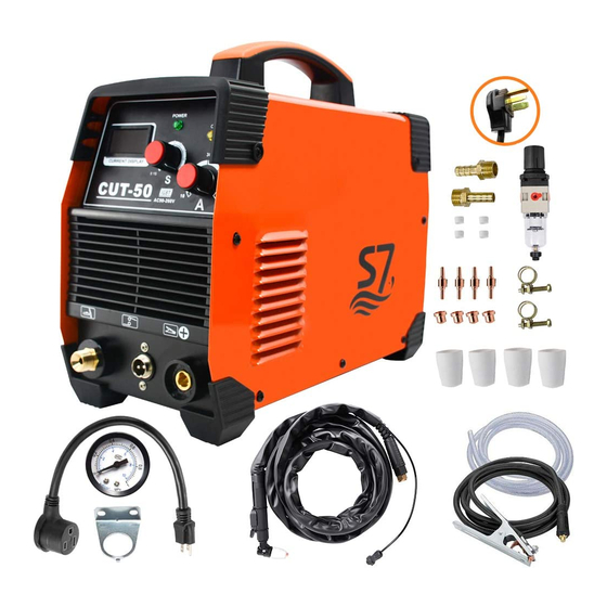
- Page 1 INVERTER PLASMA CUTTER OWNER'S MANUAL MODEL: CUT50 (POWER IGBT CONTROLIED,DC WELDING POWER SOU Website:https://s7-welder.myshopify.com Facebook/email : holafrank2014@outlook.com...
-
Page 2: Products Introduction
PRODUCTS INTRODUCTION Congratulations for your purchase CUT-50 is Inverter plasma cutter series which is made by intemational most advantaged invert technical. Inverter cutting power supply is inverter cutting machine which is sprung up in 1980s in international market 50Hz/60Hz frequency is inverted to high frequency (frequency is over 50KHz) by IGBT, then step down voltage and rectificate current, inverter cutting power supply generates powerful DC cutting current through PWM technical. -
Page 3: Main Technical Data
MAIN TECHNICAL DATA Data CUT50 Item Single phase Single phase Power voltage(v) 110V±15% 220V±15% Rate input Power(KVA) No-load voltage(v) 240±5% 240±5% Rate output current(A) Rate output voltage(V) Duty cycle Burner inter Diameter(mm) 0.8-1.0 0.8-1.0 Pressure of air Compressor(kg) ≥4 ≥4... - Page 4 OPERATION AND INSTALLATION DIAGRAM...
-
Page 5: Installation
INSTALLATION Input cable connection (enclose installing diagram) 1. Every machine has been disposed a power cable which must be connected to coordinated voltage class in compliance according to input voltage of cutting machine. 2. Make sure power cable is connected to power switch reliably and prevent from oxidizing. -
Page 6: Instruction Notes
5. It is 1mm from copper tip to work piece (it is further if it is arc- supporting cutter ),press knob of torch and burn and strike are sparks of HF arc-striking will diminished immediately. User can begin to cut. INSTRUCTION NOTES Operation environment 1. -
Page 7: Maintenance And Check Trouble
5. Inter heat-variable component is starting if machine is exceeded in duty cycles.that will cause cutting machine will stop working suddenly and inter red diode is lit.User need not break the circuit and the fan may continue working in order to cool down the machine . -
Page 8: Check Fault
CHECK FAULT Faults Resolvable Methods 1.Switch indicator is on, fan is 1. Over voltage protection is not working and control knob working. Close machine then open it is out of work. again after several minutes. 1. Check if torch is open cicuit. 2.Switch indicator is lit and fan is working.
Need help?
Do you have a question about the CUT50 and is the answer not in the manual?
Questions and answers
Do you have a chart for setting you machine at for all thickness
The thickness setting chart for the S7 CUT50 machine, based on the available context, indicates a thickness range of 1-8 mm and 1-10 mm. However, no further details or a complete chart are provided.
This answer is automatically generated
What do i need to set my regulator psi at
The regulator PSI should be set to 50 PSI at 110V and 60 PSI at 220V for the S7 CUT50 plasma cutter.
This answer is automatically generated