
Related Manuals for Waterway OASIS


Summary of Contents for Waterway OASIS
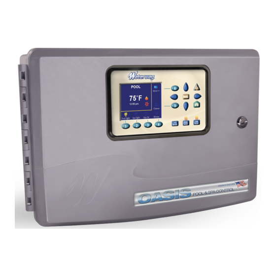
- Page 1 INSTRUCTION MANUAL POOL & SPA CONTROL Designed, Engineered & 2200 E. Sturgis Road, Oxnard, CA 93030 • Phone 805.981.0262 • Fax 805.981.9403 Manufactured waterway@waterwayplastics.com • www.waterwayplastics.com in the USA.
-
Page 2: Section 1. Important Safety Instructions
OASIS POOL & SPA CONTROL WARNING! Qualified Technician Required for Service and Installation FOR YOUR SAFETY This product must be installed and serviced by a contractor who is licensed and qualified in pool equipment by the jurisdiction in which the product will be installed, where such state or local requirements exist. In the event no such state or local requirement exists, the maintainer must be a professional with sufficient experience in pool equipment installation and maintenance, so that all of the instructions in this manual can be followed exactly. -
Page 3: Risk Of Electric Shock
DANGER Risk of electric shock: Install the controller at least five (5) feet (1.52m) from the inside wall of the pool and/or spa/hot tub using non-metallic plumbing. Canadian installations must be at least three (3) meters from the water. Children should not use spas or hot tubs without adult supervision. Do not use spas or hot tubs unless all suction guards are installed to prevent body and hair entrapment. -
Page 4: Section 2. System Overview
Section 2. System Overview Package Contents Package contents will vary depending on which OASIS configuration you are installing. OASIS - 770-1006-PSW2 OASIS - 770-1002-PS2 • Six Function Controller with removable User Interface (UI) • Six Function Controller with removable User Interface (UI) •... -
Page 5: Materials And Tools
Materials and Tools Package contents will vary depending on which OASIS configuration you are installing. Installation Materials Furnished • Screw Set (includes Plastic Anchors) • Metal Mounting Bracket Tools Needed for Installation • Power Drill • 3/16” Drill Bit - Hammer Drill Bit (only necessary to drill into brick or concrete) •... -
Page 6: Section 4. High Voltage Wiring
All high voltage wiring must be done by a licensed electrical contractor. means of disconnection, circuit isolation, and/or branch circuit protection installed upstream of the power/control center. NOTE: See Figure 10.4 OASIS Electrical Wiring Diagram on page 10 for specific wire locations and connections. -
Page 7: Ground Fault Circuit Interrupter
Ground Fault Circuit Interrupter Connect Line Power and Load Filter Pump to Relay WARNING As marked in the controller enclosure, Relay 1 is the dedicated Filter Pump relay. When using electrical products, basic precautions should always be followed, including the following: •... -
Page 8: Section 5. Low Voltage Wiring
Section 5. Low Voltage Wiring 5.1.1 Install the Water Temperature Sensor All low voltage wiring should be run through the knockouts in the low voltage compartment (right side of controller enclosure). See Figure 4. 1. Drill a hole for mounting the water temperature sensor line in the pipe between the pump and the filter (before the IMPORTANT heater). - Page 9 OASIS WiFi instruction manual. 5.2.1 Mount the OASIS WiFi Figure 6. Air Temp Sensor Mount the OASIS WiFi at least 6 feet off the ground and at least SENSOR CONNECTION 8 feet from motors, such as pumps or blowers, and other electrical equipment.
- Page 10 Variable Speed Connector WATERWAY OASIS TOPSIDE PANEL GROUNDING SOLAR TEMP SENSOR WATER TEMP SENSOR AIR TEMP SENSOR FILTER PUMP BREAKER BOX GROUND BLOWER OASIS WI-FI KIT Figure 10.4 OASIS Controller Electrical Wiring Diagram...
- Page 11 Speed Connector WATERWAY OASIS TOPSIDE PANEL Filter Pump-High GROUNDING Filter Pump-Low SOLAR TEMP SENSOR WATER TEMP SENSOR AIR TEMP SENSOR WiFi FILTER PUMP BREAKER BOX GROUND OASIS WI-FI KIT BLOWER Figure 10.1. OASIS Controller Electrical Wiring Diagram for 2-Speed Pump...
- Page 12 Refer to Figure 11- Figure 13 for specific wiring information The color code and order of connections varies based on the pump manufacturer and model as shown in the following pictures. manufacturers. NOTE: Waterway does not assume responsibility for software changes by other pump...
- Page 13 • BLACK - NUMBER 4 (WVAs) (if applicable) WATERWAY VSP2 CONNECTION TO You may wire up to four WVAs on the OASIS. Two (2) WVAs are POWER DEFENDER 300 PUMP included in optional PS2 and PSW2 Pool/Spa kits. Additional WVAs may be required on a pool/spa configuration to control a water Figure 11.3 Note: Switch 3 must be moved to UP position...
-
Page 14: Section 6. System Setup, Programming And Testing
Then the Filter pump will PARTY Mode device selection screen, MENU will be used to select turn ON if the OASIS is not in “POOL – OFF” mode. or deselect the device. - Page 15 – If the system has Solar, the solar valve must use “J3 SOLAR” and be configured for ‘Solar’, otherwise this valve can be assigned to any option. NOTE: ‘Installer Setup’ is necessary to configure the OASIS Pool Controller for each specific installation. Please pay special attention to the instructions above.
- Page 16 In this screen use the UP/DOWN buttons to > Reset Network: this option clears the OASIS Wifi setting. select the pool mode, then press the MENU/RIGHT button to enter With “Reset Network” highlighted, press MENU or RIGHT buttons the accessories selection menu.
Need help?
Do you have a question about the OASIS and is the answer not in the manual?
Questions and answers