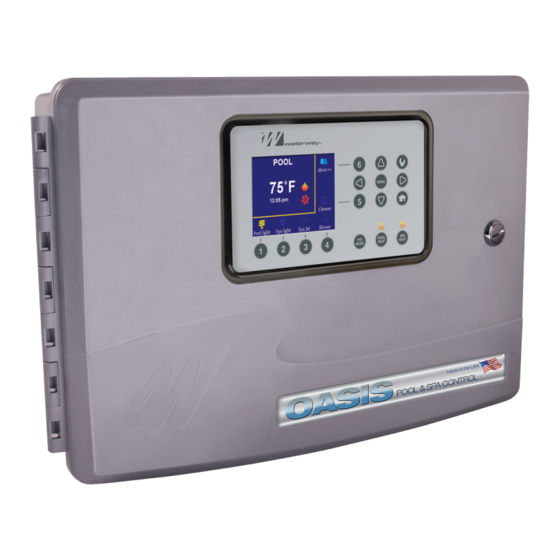
Summary of Contents for Waterway Oasis 770-1004-PSW
- Page 1 INSTRUCTION MANUAL POOL & SPA CONTROL Designed, Engineered & 2200 E. Sturgis Road, Oxnard, CA 93030 • Phone 805.981.0262 • Fax 805.981.9403 Manufactured waterway@waterwayplastics.com • www.waterwayplastics.com in the USA.
-
Page 2: Section 1. Important Safety Instructions
OASIS POOL & SPA CONTROL WARNING! Qualified Technician Required for Service and Installation FOR YOUR SAFETY This product must be installed and serviced by a contractor who is licensed and qualified in pool equipment by the jurisdiction in which the product will be installed, where such state or local requirements exist. In the event no such state or local requirement exists, the maintainer must be a professional with sufficient experience in pool equipment installation and maintenance, so that all of the instructions in this manual can be followed exactly. -
Page 3: Risk Of Electric Shock
DANGER Risk of electric shock: Install the controller at least five (5) feet (1.52m) from the inside wall of the pool and/or spa/hot tub using non-metallic plumbing. Canadian installations must be at least three (3) meters from the water. Children should not use spas or hot tubs without adult supervision. Do not use spas or hot tubs unless all suction guards are installed to prevent body and hair entrapment. -
Page 4: Section 2. System Overview
• Six Function Controller with removable User Interface (UI) • Six Function Controller with removable User Interface (UI) • OASIS WIFI • Waterway Valve Actuators (2) • Waterway Valve Actuators (2) • Water Temperature Sensor Kit • Water Temperature Sensor Kit •... -
Page 5: Materials And Tools
Materials and Tools Package contents will vary depending on which OASIS configuration you are installing. Installation Materials Furnished • Screw Set (includes Plastic Anchors) • Metal Mounting Bracket Tools Needed for Installation • Power Drill • 3/16” Drill Bit - Hammer Drill Bit (only necessary to drill into brick or concrete) •... -
Page 6: Section 4. High Voltage Wiring
UI to the controller unit. WARNING Waterway Plastics recommends that any procedure requir- NOTE: The UI MUST be mounted OUTDOORS where a pool ing potential contact with live electrical wiring and/or parts service technician may conveniently access it. -
Page 7: Ground Fault Circuit Interrupter
Ground Fault Circuit Interrupter Connect Line Power and Load Filter Pump to Relay WARNING As marked in the controller enclosure, Relay 1 is the dedicated Filter Pump relay. When using electrical products, basic precautions should always be followed, including the following: •... -
Page 8: Section 5. Low Voltage Wiring
Section 5. Low Voltage Wiring 5.1.1 Install the Water Temperature Sensor All low voltage wiring should be run through the knockouts in the low voltage compartment (right side of controller enclosure). See Figure 4. 1. Drill a hole for mounting the water temperature sensor line IMPORTANT in the pipe between the pump and the filter (before the heater). - Page 9 5.1.2 Replacing Air Sensor 5.1.4 Install Additional Low Voltage Equipment (i.e., Heater The Air Sensor comes pre-installed in the OASIS Controller. To replace the Air Sensor; Connection) 1. Remove nut located on the air sensor probe, remove probe. If there is additional low voltage equipment installed, such as low 2.
- Page 10 Variable Speed Connector WATERWAY OASIS TOPSIDE PANEL GROUNDING SOLAR TEMP SENSOR WATER TEMP SENSOR AIR TEMP SENSOR FILTER PUMP BREAKER BOX GROUND BLOWER OASIS WI-FI KIT Figure 10.4 OASIS Controller Electrical Wiring Diagram...
- Page 11 Variable Speed Connector WATERWAY OASIS TOPSIDE PANEL Filter Pump-High GROUNDING Filter Pump-Low SOLAR TEMP SENSOR WATER TEMP SENSOR AIR TEMP SENSOR WiFi FILTER PUMP BREAKER BOX GROUND OASIS WI-FI KIT BLOWER Figure 10.1. OASIS Controller Electrical Wiring Diagram for 2-Speed Pump...
- Page 12 Refer to Figure 11- Figure 13 for specific wiring information The color code and order of connections varies based on the pump manufacturer and model as shown in the following pictures. manufacturers. NOTE: Waterway does not assume responsibility for software changes by other pump...
- Page 13 OASIS WWVSP CONNECTION NOTE: Read and follow complete installation instructions and TO PD-VSC165 PUMP TO PD-VSC270 PUMP safety information in the Waterway Valve Actuator owner’s Figure 11.4 NOTE: All DIP switches should be in manual (included in the WVA packaging).
-
Page 14: Section 6. System Setup, Programming And Testing
• In MAIN screen, if no buttons are pushed within 30 minutes, the 1 - 6 around the LCD display. The accessories are shown above display will switch to display the Waterway Logo screen. Any buttons 1 - 4, and on the right of buttons 5 and 6. If there are button pushed during this time will reverse to MAIN screen. - Page 15 • RIGHT button: most of the time this will function like the MENU – Move between items in the left column with UP and DOWN. button, used to enter the settings menu and sub-menu screens. – Use the MENU or RIGHT button to navigate between columns. For screens with several settable fields, RIGHT can be used to –...
- Page 16 Any function that requires the main pump to turn on will show the Speed setting for the pump in the schedule. Designed, Engineered & Manufactured 2200 East Sturgis Road, Oxnard CA 93030 • Phone 805.981.0262 • Fax 805.981.9403 in the USA. waterway@waterwayplastics.com • www.waterwayplastics.com ©2021 Waterway Plastics 810-2110.0721...


Need help?
Do you have a question about the Oasis 770-1004-PSW and is the answer not in the manual?
Questions and answers