
Related Manuals for McIntosh MI254


Summary of Contents for McIntosh MI254
- Page 1 McIntosh Laboratory, Inc. 2 Chambers Street Binghamton, New York 13903-2699 Phone: 607-723-3512 www.mcintoshlabs.com MI254 Four Channel Power Amplifier Owner’s Manual...
-
Page 2: Table Of Contents
You now have can also return it to the McIntosh Laboratory Service 3. Included with the MI254 and located in the Own- “The Best.” The McIntosh dedication to “Quality,” is Department. For assistance on factory repair return er’s Manual Packet are two Side Rack Mounted... -
Page 3: Connector And Cable Information
Panel Channel LED will change color and the audio Output of the amplifiers. high power output per channel and will drive quality will be muted. Refer to page 15. When the MI254 Loudspeakers to a high level of performance. The has returned to a safe operating temperature, •... -
Page 4: Dimensions
MI254. Front View of the MI254 " 44.5cm " " 15/32 5/16 8.8cm 11.0cm Front View of the MI254 with Side Mount Brackets Side View of the MI254 19" 48.3cm " 47.0cm " 1/16 43.3cm "... -
Page 5: Installation
Installation " Installation 42.8cm The MI254 needs to be placed upright on its four feet. It also can be custom installed. Remove the four feet " MI254 Front Panel when it is custom installed and retain them with the 8.2cm Custom Cabinet Cutout fastening screws for possible future use. -
Page 6: Rear Panel Connections, Switches And Selection
UNBALanced Input UNBALanced Input UNBALanced Input CHANNEL 4/Left CHANNEL 3/Right CHANNEL 2/Left CHANNEL 1/Right Connect the MI254 Power Cord to a live AC Outlet BUS 1 Left and Right INput and OUTput Connections Jacks BUS 2 Left and Right INput and... - Page 7 Audio Input(s) Signal Selection Audio Input Selection for each Power Am- plifier Channel Each Channel of the MI254 allows selection of differ- Right. Each Channel of the MI254 also has UNBAL- ent Audio Signal Inputs to be Amplified via a three ANCED and BALANCED Inputs.
-
Page 8: Output Terminals And How To Connect
The size is of the MI254 Negative and Positive Caution: Do not connect the AC Power Cord to the MI254 specified in Gauge Numbers or AWG (American Wire Output Terminals, making sure to Rear Panel until after the Loudspeaker Con- nections are made. - Page 9 How to Connect for a Multi Channel System 7. Connect the MI254 power cord to an active AC outlet. Spade Lug or Wire Connections: 8. Connect the Loudspeaker hookup cables to the MI254 Output Terminal being careful to observe the correct polarities, making sure to match up channel designation with Loudspeaker location.
- Page 10 Zones B and C System Banana Plugs are for use in the United States and 5. Place the CHANNEL 3/R and 4/L Input Selector Caution: Do not connect the AC Power Cord to the MI254 Canada only: Switches to the “-2” Position.
- Page 11 For additional instruction on making Loudspeaker Connections contact your McIntosh Dealer or McIntosh Technical Support. 9. Connect the MI254 power cord to an active AC outlet. Spade Lug or Wire Connections: 10. Connect the Loudspeaker hookup cables to the...
- Page 12 C System Loudspeaker location. Loudspeaker Cable Distance vs Wire Gauge Guide Caution: Do not connect the AC Power Cord to the MI254 WARNING: Loudspeaker terminals are hazard- Rear Panel until after the Loudspeaker Connec- ous live and present a risk of electric...
- Page 13 WARNING: Loudspeaker terminals are hazard- ous live and present a risk of electric shock. For additional instruction on making Loudspeaker Connections contact your McIntosh Dealer or Mc- Intosh Technical Support. 9. Connect the MI254 power cord to an active AC outlet.
-
Page 14: Front Panel Displays And Push-Button
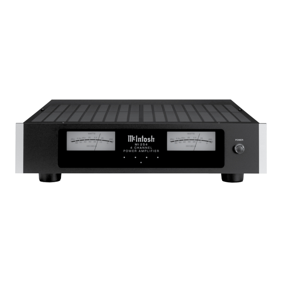
Front Panel Displays and Switch Meter indicates Left and Right Channel POWER Push-Button switches Amplifiers 1 and 2 Output AC Power On or Off Meter indicates Left and Right Channel Amplifiers 3 and 4 Output LED indicates various Channel 1 LED Standby Power LED indicates various Channel 4 Circuitry Functions... -
Page 15: How To Operate
Connectors for the same Channel where the switch is Operation Power ON/OFF to function. Both of the MI254 Power Output Meters indicate two located. Refer to pages 6 and 7 for additional informa- 3. When the MI254 is receiving a Power Control Amplifier Channels Outputs at the same time. -
Page 17: Photos
Photos... -
Page 18: Specifications
Specifications Specifications Power Output Intermodulation Distortion Power Requirements Minimum sine wave continuous average power output 0.1% maximum, if the instantaneous peak power 100 - 240Volts, 50/60Hz at 10 Amps per channel, all channels operating is: output does not exceed the rated power output for any Standby: less than 0.5 watt 250 watts into a 8 ohm load combination of frequencies from 20Hz to 20,000Hz. -
Page 19: Packing Instruction
Customer Service Depart- 017937 Plastic foot ment of McIntosh Laboratory. Refer to page 2. Please 400159 #10-32 x 3/4” screw see the Part List for the correct part numbers. - Page 20 McIntosh Laboratory, Inc. 2 Chambers Street Binghamton, NY 13903 www.mcintoshlabs.com The continuous improvement of its products is the policy of McIntosh Laboratory Incorporated who reserve the right to improve design without notice. Printed in the U.S.A. McIntosh Part No. 04189000...
Need help?
Do you have a question about the MI254 and is the answer not in the manual?
Questions and answers