Table of Contents

Related Manuals for Siemens Simatic PG 740


Summary of Contents for Siemens Simatic PG 740
- Page 1 Preface, Contents Product Overview Installing the PG 740 SIMATIC Starting Up the PG 740 Programming Device PG 740 PG 740 Expansions Configuring the PG 740 Manual Error Diagnostics Hardware Information Glossary, Index C79000-G7076-C742-01...
- Page 2 Trademarks SIMATIC and SINEC are registered trademarks of SIEMENS AG. Third parties using for their own purposes any other names in this document which refer to trademarks might infringe upon the rights of the trademark owners. Copyright...
- Page 3 Preface What this Manual This manual contains all the information you need for working with the is About PG 740 programming device. You can use it to unpack the programming device and power it up. familiarize yourself with the functions and settings of the various components (display, keyboard, programming facilities etc.).
- Page 4 Queries If you have any questions concerning subjects not covered in the manual, just get in touch with the Siemens representative in your area. If you have any questions on the manual itself or would like to make remarks or suggestions, please complete the reply card at the end of the manual. We would also appreciate it if you would include your own personal opinion on, and appraisal of, the manual on the reply card.
-
Page 5: Table Of Contents
Contents Product Overview ............Installing the PG 740 . - Page 6 Contents 5.1.1 The Main Menu ..........5.1.2 The Advanced Menu .
-
Page 7: Product Overview
Product Overview Application The PG 740 programming device is a high-performance device, equipped with the optimum hardware features and software for programming, debugging, and starting up programmable controllers in an automation environment. Hardware/Software You can use the PG 740 programming device to program SIMATIC S5 and Complement SIMATIC S7 programmable controllers. - Page 8 Product Overview Advantages of Compared to a PC with standard hardware and software, the PG 740 the PG 740 programming device of the SIMATIC family has numerous advantages: You can develop, debug and document user programs for SIMATIC S5 and SIMATIC S7 programmable logic controllers with the PG 740 without the need for additional hardware or software.
-
Page 9: Installing The
Installing the PG 740 What Does this This chapter describes how you install your PG 740. It provides you with Chapter Contain? comprehensive information on the major components of the PG 740, such as: drives keyboard, and programming facilities. Summary of In Section You Will Find On Page... -
Page 10: Setting Up The
Installing the PG 740 Setting up the PG 740 Unpacking the Unpack your PG 740 as follows: PG 740 1. Remove the packing. 2. Do not throw the original packing away. Keep it in case you have to transport the unit again sometime in the future. 3. - Page 11 Installing the PG 740 Changing the With the keyboard open, you can incline the unit to any angle between 0 and Angle of 90 around the axis of rotation of its stand. Proceed as follows: Inclination 1. Swing the keyboard down. 2.
- Page 12 Installing the PG 740 Horizontal If you do not have a desk or table on which to mount the unit, you can work Mounting with it standing on the floor. You can swing the casing with display through about 90 into the horizontal plane. Pivot Stand Extra pull-out support...
- Page 13 Installing the PG 740 You detach the keyboard as follows: 1. Grip the keyboard hinges in the stand behind the keyboard as shown in Figure 2-4. 2. Pull the locks in the middle of the hinge assembly toward the keyboard. 3.
-
Page 14: Hardware Components Of The
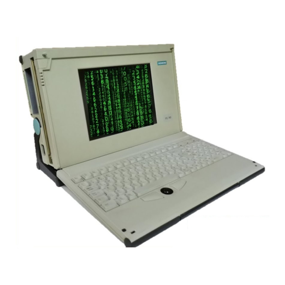
Installing the PG 740 Hardware Components of the PG 740 Front You can access all important operator controls and displays from the front or sides of the unit. On/Off switch Carrying handle LED displays LC display Ventilating slots Cover for submodule, memory card, PCMCIA interfaces and floppy disk drive Power Stand... - Page 15 Installing the PG 740 Left Hand Casing All the connectors and interface ports for connecting to external devices are Side Panel located on the left-hand side panel of the PG 740 (communications side). (Communications Side) VGA port Power switch Dummy plates LEDs covering expansion slots...
- Page 16 Installing the PG 740 Right-Hand Casing You access the slots for S5/S7 memory submodule programming, the Side Panel PCMCIA port and the disk drive from the right-hand side panel of the (Processing Side) PG 740’s casing (processing side). Ventilating slots Memory card port S5 EPROM/EEPROM port Ejector for PCMCIA...
-
Page 17: Display
Installing the PG 740 Display The PG 740’s Color The PG 740 has a TFT (thin-film transistor) color display with a 10.4 in. Display diagonal and a resolution of 800 x 600 pixels. Figure 2-9 The PG 740’s Color Display Color Shades The three primary colors, red, green and blue, can each be displayed in six different shades. -
Page 18: Keyboard
Installing the PG 740 Keyboard Keyboard Layout The keyboard is divided into the following three areas: Alphanumeric or typewriter keyboard Numeric keypad with cursor control keys Function keys Scroll Print Pause Break SysRq @ ” ^ & & / Home - ß... - Page 19 Installing the PG 740 Typewriter or The largest block of keys on the keyboard is the alphanumeric or typewriter Alphanumeric keyboard with all the keys for the letters of the alphabet, numerals and Keyboard special characters. The characters (letters, numerals and special characters) are arranged in generally the same way as on a normal typewriter.
- Page 20 Installing the PG 740 Function NUM Key You switch from the numeric block to cursor control with this key (Num LED lights up). Press the key again to return to cursor control. Tabulator Key This key moves the cursor by one or more positions to the right. “Fn”...
- Page 21 Installing the PG 740 Cursor keys The keyblock shown below is used for cursor control. Home Move cursor to beginning of file Page back Page Move cursor up Page forward Page Move cursor to end of file Move cursor left Move cursor right Move cursor down Figure 2-12...
- Page 22 Installing the PG 740 Keys for Functions The following function keys have specific functions in conjunction with the Specific to S5 STEP 5 programming software (see STEP 5 Manual). Home Horizontal expand Vertical expand Insert Enter key Cursor right/ cursor left Title/comment input for segment End of segment...
- Page 23 Installing the PG 740 Key Combinations The various key combinations are shown in Table 2-1. Table 2-1 Key Combinations Key Combination Function Warm restart CTRL Changeover to international character set CTRL Changeover to German character set; the German character set must have already been loaded.
-
Page 24: Trackball
Installing the PG 740 Trackball Trackball The trackball serves as an input device for cursor control and menu selection in many programs (with mouse operation). By moving the trackball, the cursor can be repositioned on the screen. By pressing the left-hand button, you set a marker. The right-hand button is assigned differently according to the application. - Page 25 Installing the PG 740 Figure 2-14 Cleaning the Trackball Figure 2-15 Cleaning the Trackball Housing Figure 2-16 Cleaning the Rollers Programming Device PG 740 2-17 C79000-G7076-C742-01...
-
Page 26: Drives
Installing the PG 740 Drives Drive Types The PG 740 is equipped as standard with a 3.5” diskette drive and a 3.5” hard disk drive. Diskette Drive You can store programs and data on diskettes with the diskette drive and load them from diskettes into the PG 740. - Page 27 Installing the PG 740 Self-Test Every time the PG 740 is switched on or reset, the hard disk drive performs a self-test, which is repeated during operation. Whenever the hard disk drive is accessed, the access LED on the front of the unit lights up.
-
Page 28: Transport
Installing the PG 740 Transport Preparatory The PG 740 is easy to transport. Before transporting it, however, you should Measures take the following measures: 1. Switch the PG 740 off. 2. Unplug all connecting cables. 3. Close the covers protecting the ports and connections on the right-hand and left-hand casing side panels. - Page 29 Installing the PG 740 Caution Risk of mechanical damage! Moisture or condensation in the unit can result in defects. When transporting your PG 740 in cold weather when it may be exposed to extreme variations in temperature, make sure that no moisture or condensation can form on or in the unit.
-
Page 30: Starting Up The
Starting Up the PG 740 What does this This chapter describes what you have to do to set up your PG 740 Chapter Contain? successfully for operation. This includes the basic steps for starting up your PG 740 working with memory submodules and cards for the programmable controllers connecting your PG 740 to other devices. -
Page 31: Connecting The Pg 740 To The Power Supply
Starting Up the PG 740 Connecting the PG 740 to the Power Supply Connecting to the You can operate the PG 740 on 115 V and 230 V power systems. The voltage Power Supply is selected automatically. 1. Plug the power supply cable supplied with the unit into the connector labeled ”Power”. -
Page 32: Connecting I/O Devices
Starting Up the PG 740 Connecting I/O Devices Recommended Siemens printers with parallel interface and IBM character set are Printers recommended for use with the PG 740 programming device. Printer Connection To connect your printer, proceed as follows: Via the Parallel 1. - Page 33 Starting Up the PG 740 Printer Connection You can also connect your printer to the PG 740 through a serial COM port. Via a Serial Port You will find information on how to adapt and set your interface and on the connecting cable you require in your printer manual.
- Page 34 Recommended You connect external multisynchronous monitors to the right-hand casing Monitors side panel with the standard VGA connector. We recommend you use Siemens monitors. Connecting You must switch the PG 740 off before connecting the monitor cable. You Monitors will find more details in the connector pinout in Chapter 7.
- Page 35 Starting Up the PG 740 Switching When the PG 740 is powered up, the system automatically recognizes the Additional additional graphics card. The display and the built-in VGA graphics interface Graphics Cards module are switched off. To switch the display and the built-in VGA graphics On and Off interface module back on, proceed as follows: 1.
- Page 36 Starting Up the PG 740 Switching over Once you have plugged in the external mouse and restarted your PG 740, the between Internal internal trackball is inactive, and remains inactive until the PG 740 is Trackball and PS/2 powered up again without the external mouse. Mouse Table 3-1 Trackball/External Mouse Mode...
- Page 37 Starting Up the PG 740 Choosing Another You can connect another PS/2 keyboard to the PG 740 instead of the one Keyboard supplied with it. Extra pull-out support Coverplate Keyboard cable Figure 3-5 Connecting a PS/2 Keyboard Connecting a You connect the keyboard as follows: PS/2 Keyboard 1.
-
Page 38: Working With Simatic S5 Memory Submodules
Starting Up the PG 740 Working with SIMATIC S5 Memory Submodules Working with You can read and program SIMATIC S5 EPROMs and EEPROMs via the SIMATIC S5 48-pin S5 EPROM and EEPROM programming port. You will find details on EPROMs and how to use the programming software in the STEP 5 Manual. -
Page 39: Working With Simatic Memory Cards
Starting Up the PG 740 Working with SIMATIC Memory Cards Working with You can read, program or erase SIMATIC memory cards via the 68-pin Memory Cards programming port. Orientation point SIMATIC memory cards Figure 3-7 SIMATIC Memory Cards Proceed as follows when working with the SIMATIC memory cards: 1. -
Page 40: Working With Pcmcia Cards
Starting Up the PG 740 Working with PCMCIA Cards PCMCIA Cards The PG 740 has a PCMCIA interface port of type II. You can plug communications cards for MODEM, FAX-MODEM, ISDN, token ring, ETHERNET, memory expansion and SCSI interface cards in credit-card format into this port. -
Page 41: Connections (Point-To-Point Connections)
Starting Up the PG 740 PG 740 Connections (Point-To-Point Connections) Point-to-Point In this section, you will learn how to connect your PG 740 to a programming Connection device or programmable controller over a point-to-point connection. You establish a point-to-point connection by connecting the PG 740 to another programming device or a programmable controller via a V.24 connection a TTY connection... - Page 42 Starting Up the PG 740 Connecting the If you want to connect your PG 740 to another programming device, you can PG 740 to Other plug the appropriate connecting cable into the V.24 or TTY interface port. Programming You will find the necessary information on the connecting cables listed below Devices in Chapter 7.
- Page 43 Starting Up the PG 740 Connecting the You can connect the PG 740 to a SIMATIC S5 programmable controller via PG 740 to S5 the COM1/TTY interface port. The cable for establishing the connection to Programmable the SIMATIC S5 CPUs is included with the PG 740. Controllers (Order No.
- Page 44 Starting Up the PG 740 Connecting the The connecting cable 6ES5 734-2BD20 is supplied with the PG 740. An PG 740 via an adapter is available for connecting the programmable controller using old Adapter standard cables. Interface Link Connecting Cable Adapter 6ES5 734-2BD20 PG 740 to...
-
Page 45: Multipoint Interface (Mpi/Dp)
Starting Up the PG 740 Multipoint Interface (MPI/DP) Connection of an You can connect your PG 740 to a SIMATIC S7 programmable logic S7 Programmable controller using the floating MPI/DP interface. The MPI cable for connection Controller via the to SIMATIC S7 CPUs is supplied with the PG 740 (Order No.: MPI/DP Interface 6ES7901-0BF00-0AA0). - Page 46 Starting Up the PG 740 MPI/Profibus-DP Up to 32 devices (PC, programming device or programmable controller) can Network be connected to the MPI/DP interface to form a network segment. The physical coupling of the MPI/DP interface to the PROFIBUS DP network is via a floating RS485 interface which is a component of the PG basic module.
-
Page 47: Sinec L2
Starting Up the PG 740 SINEC L2 Networking SINEC L2 is an open and ruggedly designed bus-type local area network PG 740s via (LAN) for industrial applications. It can be used to configure networks with SINEC L2 up to 127 stations. SINEC L2 has a data transfer rate of 1.5 million bps. (PROFIBUS) Principle of SINEC L2 operates on the master-slave principle with token passing (to... -
Page 48: Sinec H1
Starting Up the PG 740 SINEC H1 Networking SINEC H1 is an industry-standard bus-type local area network (LAN) based PG 740s via on ETHERNET (ISO 8802/3), and has the following characteristic features: SINEC H1 high speed (10 Mbps), simple expansion capability, open communications (ETHERNET) and widespread application. -
Page 49: Pg 740 Expansions
PG 740 Expansions What Does this You can enhance the functionality of your PG 740 by installing additional Chapter Contain? modules or powerful processors. This chapter describes how to expand your PG 740. Please observe the relevant Safety Guidelines. Summary of In Section You Will Find On Page... -
Page 50: Opening The Unit
Limitation of All technical specifications and licenses apply only to expansion functions Liability approved by Siemens. No liability can be assumed for functional constraints caused by the use of devices and components of other manufacturers. All modules and components in the PG 740 are electrostatically sensitive. - Page 51 PG 740 Expansions Tools Use a suitable TORX or Phillips screwdriver to loosen the M3 combi TORX screws. Opening the Open your PG 740 as follows: PG 740 1. Switch off the PG 740, pull out the power plug and remove all connecting cables.
-
Page 52: Functional Units Visible After Opening The Unit
PG 740 Expansions Functional Units Visible after Opening the Unit Functional Units The functional units are visible once you have removed the top section of the unit. Bus board with ISA and shared Drives PCI/ISA slots Ventilator Power supply Motherboard Bracing Expansion module (not part of basic shipping) - Page 53 PG 740 Expansions Mother board The motherboard is the heart of the PG 740. Here, data are processed and stored, and interfaces and device I/Os controlled and managed. X402 X800 123456 123456 Batt. X600 X701 X700 Figure 4-3 Motherboard Programming Device PG 740 C79000-G7076-C742-01...
- Page 54 PG 740 Expansions Components on The following components are located on the motherboard of the PG 740: the Motherboard Designation Name Functions Slotbus ISA/PCI connector between basic module and bus module HD prim. Primary IDE interface, standard ribbon cable Floppy disk Floppy disk interface Keyboard DIN keyboard plug...
- Page 55 PG 740 Expansions Switch Position Change the switch position as shown in Fig. 4-4: passive active TTY-receive TTY-send Settings must not be changed. Figure 4-4 Switching the TTY Port to Actve / Passive with the S1 Switch Programming Device PG 740 C79000-G7076-C742-01...
- Page 56 PG 740 Expansions Switch Settings S1 Manufacturer-specific settings The following switch settings are only listed for information purposes. They are set in the factory and must not be changed. x means that this switch is irrelevant to the described function. S1 (3) S1 (2) S1 (1)
- Page 57 PG 740 Expansions Standard Settings Figure 4-5 Standard Settings of Switches S1 (1..6) and S2 (1..6) for 133 MHz Pentium Clock Settings S2(6) S2(5) S1(6) S1(5) ISA-Bus PCI-Bus CPU-Bus CPU-Core Clock Clock Clock Clock (CPU internal) 8.25MHz 33MHz 66MHz 133MHz 7.50MHz 30MHz 60MHz...
-
Page 58: Installing Expansion Modules
PG 740 Expansions Installing Expansion Modules Installing You can extend the functionality of your PG 740 by installing additional Expansion modules. Two expansion slots are provided on the bus board for this purpose. Modules The following modules can be fitted: Slot Module 200 mm long... - Page 59 PG 740 Expansions Caution Risk of damage! The electronic components of the printed-circuit boards are extremely sensitive to electrostatic discharge. Please observe the guidelines for electrostatically sensitive devices (ESD guidelines), otherwise the module or device may be damaged. Plugging in the You plug expansion modules in as follows: Module 1.
-
Page 60: Installing Memory Expansion Cards
PG 740 Expansions Installing Memory Expansion Cards Standard Memory There are four slots for 36-bit SIMM memory expansion cards on the motherboard. You can expand the memory capacity of your PG 740 up to 128 MB using these memory banks. Pairs of cards must always be inserted. EDO RAMs, fast-page-mode, single-sided and double-sided SIMMs are supported. - Page 61 PG 740 Expansions Caution Risk of damage! The electronic components of the printed-circuit boards are highly sensitive to electrostatic discharge. When handling the boards or cards, you must follow the guidelines for electrostatically sensitive components (ESD guidelines) at the end of this book. Installing the SIMM Plug the SIMM memory cards in as follows: Cards...
- Page 62 PG 740 Expansions Caution Expansion cards are sensitive components. It is essential that you observe the information in the manual (Section 4.4). 5. Close the device (see Section 4.8). Caution Risk of damage! The cards must sit firmly in their sockets, otherwise they might be damaged. Plug the cards into their sockets vertically before locking them in position.
-
Page 63: Installing A Cache
PG 740 Expansions Installing a Cache Installing a Cache The motherboard has a socket for an external second-level cache. You can use this cache to enhance your processor power. Cache socket Figure 4-8 Location of the Cache You can obtain the order number for the second level module from the Product Bulletin. -
Page 64: Back-Up Battery
PG 740 Expansions Back-Up Battery Battery Power A back-up battery (3.6 V lithium battery) powers the real-time clock even Supply for after the PG 740 is switched off. In addition to the time of day, all the Real-Time Clock information about the PG 740’s configuration is stored in RAM. If the and Configuration back-up battery fails or is removed, all this data is lost. -
Page 65: Processor Upgrade
PG 740 Expansions Processor Upgrade You can increase the power of your PG 740 by installing other processors. Please contact your nearest service center or sales representative for more information. Closing the Unit Closing the Unit To close the unit, proceed as follows: 1. - Page 66 Configuring the PG 740 What Does this In this chapter, you will learn how to configure your programming device. Chapter Contain? This will be necessary if you have made any changes to your system by adding, removing or replacing an adapter card, a memory expansion card or a system module.
-
Page 67: Changing The System Configuration With Setup
Configuring the PG 740 Changing the System Configuration with SETUP Changing the Your PG 740 configuration is set for working with the software supplied with Configuration the unit. You should only change the preset values if you have modified your PG 740 in any way or if a fault occurs when the unit is powered up. - Page 68 Following below appears following power-on: Power On PhoenixBIOS Version 4.05 Copyright 1985-1995 Phoenix Technologies Ltd., All Rights Reserved. SIEMENS PG 740 Pentium CPU = Pentium 100 MHz 0000640K System RAM Passed 0015360K Extended RAM Passed System BIOS shadowed Video BIOS shadowed UMB upper limit segment address: F2xx Press <F2>...
- Page 69 Configuring the PG 740 Menu Structure The screen is divided into four parts. In the top part, you can select the menu forms [Main], [Advanced], [Security], [Power], [Exit]. In the left of the center part you can select various settings or submenus. Brief help texts appear on the right for the currently selected menu entry.
-
Page 70: The Main Menu
Configuring the PG 740 5.1.1 The Main Menu PhoenixBIOS Setup-Copyright 1992-93 Phoenix Technologies Ltd. Main Security Power Exit Item Specific Help System Time: 14:23:58 System Date: 04/06/1994 Shift-Tab , or Enter Diskette A: 1.44 MB, 31/2“ selects field. Diskette B: Not Installed xxx MB Fixed Disk 0 Type:... - Page 71 Configuring the PG 740 System Time and System Time and System Date indicate the current values. Once you have System Date selected the appropriate option, you can use the [+] and [–] keys to modify the time setting Hour:Minute:Second and the date Month/Day/Year.
- Page 72 Configuring the PG 740 IDE Adapter A branch is made to the following submenu when you select this type of Hard Disk Drive menu option: PhoenixBIOS Setup-Copyright 1985-95 Phoenix Technologies Ltd. Main Advanced Security Power Exit IDE Adapter 0 Master (C: 853 Mb) Item Specific Help Autodetect Fixed Disk [Press Enter]...
- Page 73 Configuring the PG 740 “ Multi-Sector The number of sectors which are transmitted per interrupt are transferred in the Transfers” Option option “Multi-Sector Transfers”. The value depends on the drive and should only be set using the autodetect function. Disabled 1 sector 2,4,6,8,16 Sectors...
- Page 74 Configuring the PG 740 “Memory Cache” The following submenu appears when you select the option “Memory cache” Option in the main menu: PhoenixBIOS Setup-Copyright 1985-95 Phoenix Technologies Ltd. Main Advanced Security Power Exit Memory Cache Item Specific Help Cache: [Enabled] Cache Controls.
- Page 75 Configuring the PG 740 “Memory Shadow” The following submenu appears when you select the option “Memory Option shadow” in the main menu: PhoenixBIOS Setup-Copyright 1985-95 Phoenix Technologies Ltd. Main Advanced Security Power Exit Memory Shadow Item Specific Help System shadow: Enabled Video BIOS may be copied to shadow RAM for increased...
- Page 76 Configuring the PG 740 “Boot Sequence” The following submenu appears when you select the option ”Boot Sequence” Option in the main menu: PhoenixBIOS Setup-Copyright 1985-95 Phoenix Technologies Ltd. Main Advanced Security Power Exit Boot Options Item Specific Help Boot sequence: [A: then C:] Order system searches drives for a boot disk.
- Page 77 Configuring the PG 740 Example of a summary screen: PhoenixBIOS 1985-95 Phoenix Technologies Ltd. Pentium CPU [100MHz]: F28C - FFFF System ROM: Coprozessor: Installed BIOS Date: 11/14/95 System RAM: 640 Kb COM Ports: 03F8, 02F8 Extended RAM: 15360 Kb LPT Ports: 0378 Shadow RAM: 384 Kb...
- Page 78 Configuring the PG 740 “Hardware The following submenu appears when you select the option “Hardware Options” Options” Option in the main menu: PhoenixBIOS Setup-Copyright 1985-95 Phoenix Technologies Ltd. Main Advanced Security Power Exit PG 740 Hardware Options Item Specific Help Configure MPI Adr.-Range: [Adr.
- Page 79 Configuring the PG 740 Entry Function CRT/LCD LCD enabled All data are only output on the internal LCD, selection the 15-contact VGA interface is switched off. CRT enabled For highest resolution, the display signals are only output on the 15-contact VGA interface, the LCD interface of the VGA controller is switched off.
-
Page 80: The Advanced Menu
Configuring the PG 740 5.1.2 The Advanced Menu Menu Structure PhoenixBIOS Setup-Copyright 1985-95 Phoenix Technologies Ltd. Main Advanced Security Power Exit Item Specific Help Warning! Setting items on this menu to incorrect va- lues may cause your system to malfunction. PCI Devices Plug &... - Page 81 Configuring the PG 740 Large Disk [DOS] The drive tables are designed according to Access Mode DOS drive access operations compatible with enhanced IDE. [OTHER] The tables are not adapted. VGA Interrupt [Enabled] IRQ 9 is reserved for the VGA card. [Disabled] IRQ 9 is reserved for other devices.
-
Page 82: The Security Menu
Configuring the PG 740 5.1.3 The Security Menu Summary You can only edit the options enclosed in square brackets. Two passwords are assigned to protect your programming device from unauthorized use. You can use the supervisor password to prevent use of diskettes for the normal user and to limit use of the hard disk. -
Page 83: The Power Menu
Configuring the PG 740 5.1.4 The Power Menu Summary This menu has the following structure: PhoenixBIOS Setup-Copyright 1985-95 Phoenix Technologies Ltd. Main Advanced Security Power Exit Item Specific Help APM: Enabled Power Savings: Disabled APM (Advanced Power Management) allows APM aware software to better Standby Timeout: Disabled manage power savings. - Page 84 Configuring the PG 740 Standby Timeout [Disabled] No standby mode [30min] Minutes after your programming device goes to standby mode [1hr][2hr][3hr][4hr] Hours after your programming goes to standby mode provided no mouse or keyboard operations have been carried out Suspend [Disabled] No suspend mode Timeout...
-
Page 85: The Exit Menu
Configuring the PG 740 5.1.5 The Exit Menu The Exit Menu The setup program is always terminated using this menu. PhoenixBIOS Setup-Copyright 1985-95 Phoenix Technologies Ltd. Main Advanced Security Power Exit Item Specific Help Save Changes & Exit Exit Without Saving Changes Exit after writing all changed SETUP Get Default Values item values to CMOS. - Page 86 Configuring the PG 740 Documenting your If you have made any modifications to your standard SETUP settings, you System can enter them in the following table. You then have ready access to the Configuration values you have set if you have to make any hardware modifications later. Table 5-1 Modifications in Device Configuration System Parameter...
-
Page 87: Pci Configuration
MS-DOS, such as Socket Services Card Services Client Drivers Flash File System from your nearest Siemens sales office or representative. Windows 95 which is already installed on delivery supports use of the PCMCIA interface. Programming Device PG 740 5-22 C79000-G7076-C742-01... -
Page 88: Error Diagnostics
Error Diagnostics What Does this Chapter 6 will support you in handling simple errors and faults that you Chapter Contain? yourself can diagnose and, in some cases, eliminate. The chapter describes all the possible errors and faults, explains their causes and makes suggestions as to how to eliminate them. - Page 89 Error Diagnostics Table 6-1 Errors/Faults in PG 740 Operation Error/Fault Cause Remedy Power-ON LED does not light up PG 740 is switched off Switch the PG 740 on Power supply not properly Check the power supply connected connections, power cable and power plug Display remains dark after power Back-lighting is not active...
-
Page 90: Hardware Information
Hardware Information What Does this This chapter contains important reference data: Chapter Contain? Hardware addresses Interrupt assignments Information on connecting cables Summary of In Section You Will Find On Page Sections Hardware Address Table Interrupt Assignments PG 740 Video Modes Connector Pinouts Connecting Cables 7-16... -
Page 91: Hardware Address Table
Hardware Information Hardware Address Table There are two kinds of address area: Memory address area I/O address area. Different read/write signals (I/O WR, I/O RD, MEMR, MEMR) are used to reference these areas. The following tables will give you an overview of the address areas used. - Page 92 Hardware Information Memory decoding The Pentium CPU has a memory address area of 4 Gbytes. The CPU has a function 64-bit wide data bus, 29 address lines (A3...A31) and 8 bus enable lines (BD0...BE7) which code the non-existent byte address lines A0, A1 and A2. The CPU address bus is mapped on the PCI address bus via the TSC (system controller).
- Page 93 Hardware Information Table 7-2 I/O Address Assignments Address Size Function from Byte Basic Function Possible Alternative Function 0000 000F PiiX DMA 1 0020 0021 PiiX PIC 1 (interrupt controller) 002E 002F Configuration port Ultra I/O 0040 0043 PiiX Timer1 (SW clock/refresh/speaker) 0060 0060...
- Page 94 Hardware Information Table 7-2 I/O Address Assignments, continued Address Size Function from Byte Basic Function Possible Alternative Function 03D0 03DF CGA/VGA control register 03E0 03E1 PCMCIA-controller can be switched off in SETUP Then vacant 03E8 03EF COM 3 not used 03F0 03F5 Floppy 1 on board...
- Page 95 Hardware Information I/O and Memory Below are listed the I/O and memory assignments of a number of expansion Assignments modules set in the factory. Please consult the relevant hardware descriptions since you can also select other settings. Table 7-4 I/O and Memory Assignments I/O Address Memory Address Module...
-
Page 96: Interrupt Assignments
Hardware Information Interrupt Assignments Interrupt The PG 740 uses two integral interrupt controllers of type 82C59 to handle Assignment the 16 hardware interrupts (IRQ 0 to IRQ 15). The INT output of the slave controller is connected to the IRQ 2 input of the master controller. -
Page 97: Pg 740 Video Modes
Hardware Information PG 740 Video Modes Table 7-6 PG 740 Video Modes Mode No. (hex) VESA- Video Mode Colors Simultaneous Mode No. (text/graphics) 00+/01+ –– Text 40x25 70Hz 60Hz 60Hz 02+/03+ –– Text 80x25 70Hz 60Hz 60Hz 04/05 –– Gr.320x200 70Hz 60Hz 60Hz... -
Page 98: Connector Pinouts
Hardware Information Connector Pinouts Connecting a PS/2 You can connect a PS/2 mouse to your PG 740. The connector has the Mouse following pinout: View of socket connector Figure 7-1 Connector Pinout for a PS/2 Mouse Connecting Cable Pin No. Designation Input/Output Data line Input/output... - Page 99 Hardware Information Connecting a You can connect an external keyboard to your PG 740. The connector has the Keyboard following pinout: View of socket connector Figure 7-2 Connector Pinout for an External Keyboard Connecting Cable Pin No. Designation Input/Output Data line, keyboard Input/output Data line Input/output...
- Page 100 Hardware Information VGA Socket The VGA socket connector on the PG 740 has the following pinout: Connector Figure 7-3 VGA Socket Connector Pin No. Designation Description Input/Output R_EXT Output G_EXT Green Output B_EXT Blue Output Ground Ground Ground Ground Ground Ground Ground Ground...
- Page 101 Hardware Information MPI/DP Socket The MPI/DP socket connector on the PG 740 has the following pinout: Connector Figure 7-4 MPI/DP Socket Connector Pin No. Designation Description Input/output Pin 1 is not assigned – Pin 2 is not assigned – LTG_B Signal line B of MPI module Input/output RTS_AS RTSAS, control signal for...
- Page 102 Hardware Information Parallel Port The parallel port (LPT1) on the PG 740 has the following pinout: Figure 7-5 LPT1 Parallel Port (Socket Connector) Pin No. Signal Designation Input/Output / Strobe Output (open collector) Data - Bit 0 Output (TTL level) Data - Bit 1 Output (TTL level) Data - Bit 2...
- Page 103 Hardware Information Serial Port (PLC/ The serial port (COM1) on the PG 740 has the following pinout: V.24/Modem) Figure 7-6 COM1 Serial Port (Socket Connector) Pin No. Designation Description Input/Output TxD (D1) Serial transmit data Output RxD (D2) Serial receive data Input RTS (S2) Request to send...
- Page 104 Hardware Information Serial Port The serial port (COM2 on the PG 740 has the following pinout: (V.24/ Mouse) Figure 7-7 COM2 Serial Port Pin No. Designation Description Input/Output DCD (M5) Data carrier detect Input RxD (D2) Receive data Input TxD (D1) Transmit data Output DTR (S1)
- Page 105 Hardware Information Connecting Cables Overview PG 6xx 6ES5731-6AG00 PLC-SS/TTY COM1/TTY 6ES5733-2xxx0 PG 7xx 6ES5733-5xxx0 COM1/V.24 COM1/V.24 Link via V.24 6ES5731-6AG00 S5-90U to S5-155U 15-pin PG IF 6ES5731-1xxx0 COM1/TTY 6ES5734-2xxx0 6ES5731-6AG00 25-pin PG IF S5-150U (AS 511) 6ES5731-0xxx0 Printer 6AP1901-0AL00 Centronics LPT1/Centronics 6ES5731-6AG00 CP523-525...
-
Page 106: Connecting Cables
Hardware Information Standard You can use the standard connecting cable (supplied along with your PG 740) Connecting Cable to connect your PG 740 a Siemens programmable controller. Please read the notes in Chapter 3. Connecting cable PG 7xx 6ES5 734-2BD20... - Page 107 Hardware Information Connecting Cable with 25-Pin Socket Connector AG-S5, V.24 PG 7xx PG 695 II Adapter Connecting cable 25-plug connector 6ES5 731–-6AG00 6ES5 731-0xxx0 25-pin socket passive port active port (Rel. 2) 330 ohms –U 330 ohms Shield –U Casing Figure 7-11 Connecting Cable with 25-Pin Socket Connector Cable for...
- Page 108 Hardware Information Connection to S5 If you want to connect your PG 740 to the S5/V.24 port of a PG 6xx PLC/V.24 and programming device, you will need an adapter. In this case, the PG 740 must COM1/TTY of a be the active programming device.
-
Page 109: Glossary
This chapter contains a glossary in which you will find a list of the Chapter Contain? terminology used in conjunction with the Siemens range of programming devices and a brief explanation of each of the terms. Programming Device PG 740... - Page 110 Glossary Access Protection Access to the programs and data of a programming device can be protected by passwords. Application An application is a program which builds directly on, for example, the operating system. Applications on your programming device are MS-DOS/Windows, the STEP 5 Basic package, GRAPH 5 etc. ASCII Editor With an ASCII editor you can process (that is, edit) text files which are stored in ASCII code (American Standard Code of Information Interchange).
- Page 111 Glossary COM2 Port The COM2 port is a serial V.24 interface which can be used to connect a mouse or a printer. Configuration These are files which define the configuration after booting. Examples of Files such files are CONFIG.SYS and AUTOEXEC.BAT. Configuration The configuration software brings the device configuration up to date when Software...
- Page 112 Glossary Drivers These are programs which are part of the operating system. They adapt the data from user programs to the specific formats required by the I/O devices such as hard disk, printers and monitors. Drop-Down Menu In graphics-supported programs, a menu line is positioned on the top edge of the screen.
- Page 113 Glossary Interface An interface is the connection between individual hardware elements such as PLCs, programming devices, printers or monitors via physical connections (cables). An interface is also the connection between different programs, to enable them to work together. Interface Module Module which controls and extends the hardware periphery.
- Page 114 Glossary Main Memory The main memory is the complete RAM memory of a programming device. Memory Card Memory submodule in credit-card format containing RAMs or EPROMs. Modem Communications device that enables a computer to send and receive data over a telephone line. Modulator and demodulator of a signal transmission facility.
- Page 115 Glossary Network Link between programming devices and programmable controllers by means of interface modules, physical cables and the corresponding software to allow data exchange between the devices. Operating System Collective term for all programs which, in conjunction with the hardware, control and monitor execution of the user programs, the distribution of resources among the individual user programs and the maintenance of the operating mode (for example, MS-DOS).
- Page 116 Glossary Programmable The programmable logical controllers (PLC) of the SIMATIC S5 system Controller consist of a central controller, one or more CPUs and various I/O modules. The PLCs of the SIMATIC S7 system (for example, S7-200, S7-300) consist of one or more CPUs and various I/O modules. Pull-Down Menu See Drop-Down Menu RAM (Random Access Memory) is a read/write memory in which every...
- Page 117 Glossary SINEC L2 Bus system on the basis of the PROFIBUS standard. Components of the SIMATIC S5 and S7 series (for example, programming device, programmable controller, remote I/O) can be networked directly using SINEC L2. SINEC H1 Bus system on the basis of the ETHERNET standard. Components of the (ETHERNET) SIMATIC S5 and S7 series (for example, programming device, programmable controller, remote I/O) can be networked directly using...
- Page 118 Glossary V.24 Interface The V.24 interface is a standardized interface for data transmission. Printers, modems and other hardware modules can be connected to a V.24 interface. (Video Graphics Array) Color graphics control mode Warm Restart A warm restart is a restart after a program has been aborted. The operating system is reloaded and restarted.
-
Page 119: Index
Index Active/passive switching, 4-6 Function keys, 2-14 Address areas, 7-2 Graphics card, 3-6 BIOS, 5-2 Hard disk drive, 2-18 Cache, 4-15 Hardware Information, 7-1 Clock, 4-16 Closing the unit, 4-17 COM 1, 2-7, 7-14 COM 2, 7-15 I/O address space, 7-2 Configuring the PG 740, 5-1 Interrupt, 7-7 Connecting cables, 7-16... -
Page 120: Pg 740 Video Modes
Index SIMATIC S7 programmable controller, 3-16 SINEC H1, 3-19 Non-heating appliances, 2-7 SINEC L2, 3-18 Special keys, 2-11 Startup, 3-1 Starting up the PG 740, 3-1 Overview/connecting cables, 7-16 Switch position, 4-7 System configuration, 5-2 Parallel port, 7-13 PCMCIA interface, 3-11 Trackball, 2-16, 3-7 PG 740 Video Modes, 7-8 Transport, 2-20... - Page 121 Siemens AG AUT E 146 Östliche Rheinbrückenstr. 50 D–76181 Karlsruhe Federal Republic of Germany From: Your Name: _ _ _ _ _ _ _ _ _ _ _ _ _ _ _ _ _ _ _ _ _ _ _ _ _ _ _ _ _...
- Page 122 Your comments and recommendations will help us to improve the quality and usefulness of our publications. Please take the first available opportunity to fill out this questionnaire and return it to Siemens. Please give each of the following questions your own personal mark within the range from 1 (very good) to 5 (poor).
Need help?
Do you have a question about the Simatic PG 740 and is the answer not in the manual?
Questions and answers