
Related Manuals for meibes SOL-BASIS

Summary of Contents for meibes SOL-BASIS
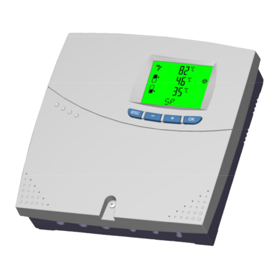
- Page 1 Universal controller for solar energy systems with one collector array and one storage reservoir COMMISSIONING MANUAL...
-
Page 2: Table Of Contents
Contents Note! Before beginning assembly or installation work, first read this commissioning manual and familiarise yourself with its content in full! The safety instructions and working instructions in the operating manual must also be observed! Take note of the settings which you make, at the respective places provided for this purpose in this commissioning manual and in the operating manual! Contents Product description ..........................3... -
Page 3: Product Description
Product description 1. Product description Your solar controller is a microprocessor-based controller, for control of solar energy systems with one collec- tor array and one storage reservoir. The pump is controlled so as to optimise the heat energy obtained from the solar collector array, according to the solar irradiation and the temperatures which arise in the solar energy system. -
Page 4: Technical Data
Technical data 2. Technical data Supply voltage 230 V AC 50 Hz Power consumption 2.4 VA Fuse 1.6 AT, microfuse 5 mm x 20 mm Inputs 4 inputs: temperature sensor: Pt1000 (-20 °C to +150 °C) Outputs 2 electromechanical relays: each 1 A, 250 V AC (ε) Protection degree IP 20 as per DIN EN 60529 (VDE 0470-1) Mode of operation... -
Page 5: Transport And Storage
Transport and storage 4. Transport and storage Thoroughly check whether the packaging or the controller shows any sign of damage. Transport the controller in the original packaging only. If the controller falls, even from a low height, it may get damaged. Prevent impact and extreme temperatures (below 0 °C or above + 50 °C) during transport and storage. -
Page 6: Possible Additional Functions
Installing and connecting the controller 5.2. Possible additional functions This table shows you the additional functions which can be used. One relay can be assigned individually. Funktion Described in section Low-Flow 10.1. 10.2. Collector monitoring / tube function 10.4. Collector safety function 10.6. -
Page 7: Installing The Controller
Installing and connecting the controller 5.6. Installing the controller Upper fastening hole (for hanging) 140mm Terminal cover Lower fastening holes Choose a suitable installation location. Remove the collector’s terminal cover. Mark and drill (Ø 6 mm) the central upper fastening hole. Insert the provided rawlplug and a screw. Hang the controller on the screw and align it. -
Page 8: Installing The Collector Sensor And Storage Reservoir Sensor
Installing and connecting the controller Electrical connections are to be realised with screw terminals (single wire / fine wire, max. 1.5 mm²). The mains supply’s protective earth connector is to be connected to the 5-pole terminal block ( Protective earth connection of loads (pumps etc.) is to be realised at the 5-pole terminal block provided for this purpose. -
Page 9: Commissioning The Controller
Commissioning the controller 6. Commissioning the controller 6.1. Front view of the controller with buttons and display : Apply current setting Open a submenu On the normal level: Select a submenu Within a menu: Scroll – For settings: Change value : Return to previous menu Discard change and restore previous value Delete input... -
Page 10: The Specialised Mechanic Level
The specialised mechanic level 7. The specialised mechanic level The specialised mechanic level contains the settings which must be set during commissioning (possibly only once). – To open the specialised mechanic level, press and hold the buttons simultane- ously for five seconds while in the normal start display. –... -
Page 11: Reset Of The Factory Setting
Reset of the factory setting 8. Reset of the factory setting – Open the specialised mechanic level (press and hold the buttons simultaneously for five – seconds) and use the button to select the sublevel E3-1. Confirm your selection with . -
Page 12: Pump Blockage Protection
Pump blockage protection Pump blockage protection If the pumps have been deactivated for a long time, there is a risk that they will block when reactivated, due to accumulated dirt or limescale. In order to prevent such blockages, the pumps are switched on for 10 sec- onds at a certain time each day. -
Page 13: Additional Function: Emergency Collector Switch-Off
Setting the additional functions 10.3. Additional function: emergency collector switch-off If collector temperature exceeds the maximum value NOT (which is set here) for longer than 5 minutes, the solar pump is switched off and will not resume operation until the collector temperature has fallen below NOT - 10 K. -
Page 14: Additional Function: Thermostat, E.g. For Activation Of The Circulation Pump
Setting the additional functions 10.7. Additional function: thermostat, e.g. for activation of the circulation pump The sensor input and relay output are freely selectable. Additional function Level Display Function Factory Range Selection setting Selection of sensor for the 0 to 4 E3-7 / 1 thermostat function. -
Page 15: Additional Function: Temperature Comparison
Setting the additional functions 10.8. Additional function: temperature comparison Sensor inputs and relay outputs can be freely selected for an additional temperature comparison function. Level Display Function Factory Range Selection setting Selection of the first sensor 0 to 4 E3-8 / 1 input. -
Page 16: System Information Menu
System information menu 11. System information menu Here, you can read information about the solar controller and define system settings. Level Display Function Factory Range Selection setting E3-10 / 1 Display of software version. E3-10 / 2 Display of hardware version. E3-10 / 3 Display of circuit board version. -
Page 17: Overview Of All Settings
Overview of all settings 12. Overview of all settings Level Dis- Function Factory Range play setting Maximum loading temperature MAX for the 70 °C 10 °C to 90 °C storage reservoir . YES / no Activation/deactivation of the storage reservoir YES / no E3-1 / 1 Reset of the factory setting. -
Page 18: Relay Test Submenu "Rel
Relay test submenu “REL” 13. Relay test submenu “REL” – To navigate to the submenu for “manual adjustment” of relays, press repeatedly until “REL” appears in the display. Call up the “relay test” sublevel by pressing the button. This causes all outputs (relays) to be switched off! The individual relays are selected by pressing –... - Page 19 Notes:...
- Page 20 The descriptions, performance specifications and graphics in this man- ual are non-binding. Subject to technical alterations. This manual may not be duplicated, distributed, altered, passed on, translated into another language or used in any other way, without the express permis- sion of the manufacturer.
Need help?
Do you have a question about the SOL-BASIS and is the answer not in the manual?
Questions and answers