
Related Manuals for York YCWL Series


Summary of Contents for York YCWL Series
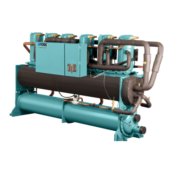
- Page 1 FORM 150.26-EG1 (116) MODEL YCWL WATER-COOLED SCROLL LIQUID CHILLER STYLE A 50 – 200 TONS 175kW – 700 kW 60Hz...
- Page 2 FORM 150.26-EG1 (116) Nomenclature YCWL 0084 DEVELOPMENT DESIGN UNIT TYPE LEVEL SERIES REFRIGERANT YORK Water Cooled Development Level A R-410A Scroll Compressor UNIT DESIGNATOR VOLTAGE CODE H = High Efficiency 17 = 200/3/60 S = Standard Efficiency 28 = 230/3/60...
-
Page 3: Table Of Contents
FORM 150.26-EG1 (116) Table of Contents EQUIPMENT OVERVIEW ............................5 MICROPROCESSOR CONTROLS ......................... 8 ACCESSORIES AND OPTIONS ........................... 11 REFRIGERANT FLOW DIAGRAM ........................14 DESIGN PARAMETERS ............................15 PRESSURE DROP CURVES ..........................16 SELECTION DATA ..............................18 APPLICATION DATA ............................. 22 RATINGS ................................ - Page 4 FORM 150.26-EG1 (116) THIS PAGE INTENTIONALLY LEFT BLANK. JOHNSON CONTROLS...
-
Page 5: Equipment Overview
FORM 150.26-EG1 (116) Equipment Overview YORK YCWL Water-Cooled chillers provide chilled water for all air conditioning applica- tions that use central station air handling or terminal units. They are completely self- contained and are designed for indoor (new or retrofit) installation. Each unit includes hermetic scroll compressors, a liquid evaporator, water cooled condenser, and a user- friendly, Microcomputer Control Center mounted on a rugged steel base. - Page 6 AHRI CERTIFICATION PROGRAM YORK YCWL chillers have been tested and certified by Air-Conditioning, Heating and Re- frigeration Institute (AHRI) in accordance with the latest edition of AHRI Standard 550/590 (I-P).
- Page 7 FORM 150.26-EG1 (116) Equipment Overview (Cont'd) POWER AND CONTROL PANELS All controls and motor starting equipment necessary for unit operation shall be factory wired and function tested. The panel enclosures shall be designed to NEMA 1 (IP 32) and manufactured from powder-painted galvanized steel. The Power and Control Panel shall be divided into a power section for each electrical system, a common input section and a control section.
-
Page 8: Microprocessor Controls
FORM 150.26-EG1 (116) Microprocessor Controls MICROPROCESSOR CONTROLS The control section shall contain: • On/Off rocker switch • Microcomputer keypad and display • Microprocessor board • I/O expansion board • Relay boards • 24V fused power-supply board The control display shall include: •... - Page 9 FORM 150.26-EG1 (116) Microprocessor Controls (Cont'd) • Low liquid temperature cutout • Low suction pressure cutout • High discharge pressure cutout • Anti-recycle timer (compressor start cycle time) • Anti-coincident timer (delay compressor starts) Unit section to: • Set time •...
- Page 10 FORM 150.26-EG1 (116) Microprocessor Controls (Cont'd) The standard controls shall include: brine chilling, automatic pumpdown, run signal con- tacts, demand load limit form external building automation system input, remote reset liquid temperature reset input, unit alarm contacts, chilled liquid pump control, automatic reset after power failure, and automatic system optimization to match operating condi- tions.
-
Page 11: Accessories And Options
FORM 150.26-EG1 (116) Accessories and Options All accessories and options are factory installed unless otherwise noted. POWER OPTIONS Single Point Supply Terminal Block - The standard power wiring connection on all mod- els is a single point power connection to a factory provided terminal block. Components included are the enclosure, terminal-block and interconnecting wiring to the compressors. - Page 12 FORM 150.26-EG1 (116) Accessories and Options (Cont'd) Differential Pressure Switch - An alternative option to the paddle-type flow switch. 3-45 PSIG (0.2-3 bar) range with ¼” NPTE pressure connections. (Field Mounted) Pressure Vessel Codes - Evaporators and condensers are be supplied (Standard) in con- formance with the A.S.M.E.
- Page 13 FORM 150.26-EG1 (116) Accessories and Options (Cont'd) VIBRATION ISOLATION Elastomeric Isolation – Recommended for normal in stallations. Provides very good per- formance in most applications for the least cost. (Field-Mounted) 1 Inch Spring Isolators – Level adjustable, spring and cage type isolators for mounting under the unit base rails.
-
Page 14: Refrigerant Flow Diagram
FORM 150.26-EG1 (116) Refrigerant Flow Diagram Low-pressure liquid refrigerant enters the evaporator tubes and is evaporated and super- heated by the heat energy absorbed from the chilled liquid passing through the evaporator shell. Low-pressure vapor enters the compressor where pressure and superheat are in- creased. -
Page 15: Design Parameters
FORM 150.26-EG1 (116) Design Parameters DESIGN PARAMETERS - STANDARD EFFICIENCY (SE) LEAVING EVAP. EQUIPMENT ENT. COND. LVG. COND. CONDENSER EVAPORATOR WATER TEMP. ROOM TEMP WATER TEMP. WATER TEMP. YCWL FLOW GPM (L/S) FLOW GPM (L/S) °F (°C) °F (°C) °F (°C) °F (°C) MODEL MIN1... -
Page 16: Pressure Drop Curves
FORM 150.26-EG1 (116) Pressure Drop Curves YCWL Evaporator Pressure Drop (English Units) Water Flow Rate (GPM) LD18404 10.0 EVAPORATOR YCWL MODEL NUMBER 0056SE, 0064SE, 0074SE, 0084SE 0064HE, 0094SE 0104SE, 0118SE 0074HE, 0084HE, 0094HE, 0118HE, 0132SE 0096HE, 0157SE 0127HE, 0157HE, 0198SE YCWL Evaporator Pressure Drop (SI Units) 100.0 Water Flow Rate (l/s) - Page 17 FORM 150.26-EG1 (116) Pressure Drop Curves (Cont'd) YCWL Condenser Pressure Drop (English Units) 100.0 10.0 1000 Water Flow Rate (GPM) LD18406 EVAPORATOR YCWL MODEL NUMBER 0056SE, 0064SE, 0074SE, 0084SE 0064HE, 0094SE 0104SE, 0118SE 0074HE, 0084HE, 0094HE, 0118HE, 0132SE 0096HE, 0157SE 0127HE, 0157HE, 0198SE YCWL Condenser Pressure Drop (SI Units) Water Flow Rate (l/s)
-
Page 18: Selection Data
Selection Data GUIDE TO SELECTION Complete water chilling capacity ratings for YORK YCWL chillers are shown on the follow- ing pages to cover the majority of job requirements. For any application beyond the scope of this Engineering Guide, consult your nearest Johnson Controls office. - Page 19 FORM 150.26-EG1 (116) Selection Data (Cont'd) 5. ETHYLENE GLYCOL CORRECTION FACTORS – The following factors are to be applied to the standard ratings for units cooling ethylene glycol. ETHYLENE GLYCOL PRESS FREEZE %WEIGHT TONS COMPR KW DROP POINT 0.993 1.002 1.029 1.095 0.980...
- Page 20 FORM 150.26-EG1 (116) Selection Data (Cont'd) Or combine the two formulas: Condenser Tons x 30 Cond. Water GPM = Condenser Water Range (ºF) SAMPLE SELECTION Water Cooled Chiller (YCWL) GIVEN – Chill 200 GPM of water from 56ºF to 44ºF and 0.0001 evaporator fouling factor with 85ºF to 95ºF condensing water available.
- Page 21 FORM 150.26-EG1 (116) Selection Data (Cont'd) 3. Determine the average full load kW and EER at 100 Tons. X (84.4) = 77.6 kW 108.8 Tons x 12 100 x 12 EER = = 15.5 77.6 4. Determine the cond. Heat rejection as follows: Heat Rejection (MBH) = (Tons x 12) + (kW x 3.415) = (108.8 x 12) + (84.4 x 3.415) = 1306 + 288...
-
Page 22: Application Data
FORM 150.26-EG1 (116) Application Data UNIT LOCATION Chillers are designed for indoor installation. Units should be located away from noise-criti- cal areas. Service clearance must be allowed and include space for remov ing condenser tubes. A doorway or window can sometimes provide space for tube removal. Units should be installed indoors where they are not exposed to rain or water splash. - Page 23 All field wiring must comply with the National Electric Code and all applicable local codes. YORK liquid chiller units are factory wired for optimum reliability. Therefore the unit con- trols must not be modified without ex pressed written consent by Johnson Controls. The use of a simple switch or timer from a remote point is permitted;...
-
Page 24: Ratings
FORM 150.26-EG1 (116) Ratings - Standard Efficiency MODEL: YCWL0056SE IPLV= 21.3 ENTERING CONDENSER WATER TEMPERATURE (°F) LCWT 75.0 85.0 95.0 TONS TONS TONS (°F) 40.0 50.7 33.9 724.0 17.9 48.1 37.7 705.0 15.3 45.3 42.0 686.0 12.9 42.0 52.6 34.1 747.0 18.5 49.8... - Page 25 FORM 150.26-EG1 (116) Ratings - Standard Efficiency (Cont'd) MODEL: YCWL0094SE IPLV= 21.6 ENTERING CONDENSER WATER TEMPERATURE (°F) LCWT 75.0 85.0 95.0 TONS TONS TONS (°F) 40.0 84.4 57.1 1207.0 17.7 80.1 63.1 1176.0 15.2 75.5 70.1 1145.0 12.9 42.0 87.5 57.4 1245.0 18.3...
- Page 26 FORM 150.26-EG1 (116) Ratings - Standard Efficiency (Cont'd) MODEL: YCWL0157SE IPLV= 23.6 ENTERING CONDENSER WATER TEMPERATURE (°F) LCWT 75.0 85.0 95.0 TONS TONS TONS (°F) 40.0 142.3 91.1 2018.0 18.7 134.2 104.9 1968.0 15.4 125.9 120.9 1923.0 12.5 42.0 147.4 90.9 2079.0 19.5...
- Page 27 FORM 150.26-EG1 (116) Ratings- High Efficiency MODEL: YCWL0064HE IPLV= 21.5 ENTERING CONDENSER WATER TEMPERATURE (°F) LCWT 75.0 85.0 95.0 TONS TONS TONS (°F) 40.0 61.9 41.1 883.0 18.1 58.8 45.9 862.0 15.4 55.4 51.1 839.0 13.0 42.0 64.1 41.3 910.0 18.6 61.0 46.1...
- Page 28 FORM 150.26-EG1 (116) Ratings - High Efficiency (Cont'd) MODEL: YCWL0096HE IPLV= 21.8 ENTERING CONDENSER WATER TEMPERATURE (°F) LCWT 75.0 85.0 95.0 TONS TONS TONS (°F) 40.0 93.8 61.3 1334.0 18.4 89.1 68.5 1302.0 15.6 84.0 76.4 1268.0 13.2 42.0 97.2 61.6 1377.0 18.9...
- Page 29 FORM 150.26-EG1 (116) Ratings - High Efficiency (Cont'd) MODEL: YCWL0127HE IPLV= 24.8 ENTERING CONDENSER WATER TEMPERATURE (°F) LCWT 75.0 85.0 95.0 TONS TONS TONS (°F) 40.0 127.0 78.7 1792.0 19.4 119.5 91.7 1747.0 15.6 112.0 106.7 1708.0 12.6 42.0 131.8 78.3 1848.0 20.2...
-
Page 30: Part Load Ratings
FORM 150.26-EG1 (116) Part Load Ratings ENGLISH STANDARD EFFICIENCY (SE) YCWL0056SE YCWL0064SE YCWL0074SE YCWL0084SE TONS KW TONS KW TONS KW TONS KW LOAD LOAD LOAD LOAD 100.0 51.6 37.9 16.3 100.0 59.9 45.7 15.7 100.0 67.8 53.6 15.2 100.0 76.6 58.3 15.8 75.0... - Page 31 FORM 150.26-EG1 (116) Part Load Ratings (Cont'd) SI STANDARD EFFICIENCY (SE) YCWL0056SE YCWL0064SE YCWL0074SE YCWL0084SE KWO KWI COP KWO KWI COP KWO KWI COP KWO KWI COP LOAD LOAD LOAD LOAD 100.0 182.4 38.1 100.0 210.7 45.7 100.0 238.5 53.6 100.0 269.3 58.3 75.0 142.9 25.6...
-
Page 32: Physical Data
FORM 150.26-EG1 (116) Physical Data - English STANDARD EFFICIENCY (SE) YCWL 0056SE 0064SE 0074SE 0084SE 0094SE 0104SE 0118SE 0132SE 0157SE 0177SE 0198SE GENERAL UNIT DATA Nominal Unit Capacity 51.6 59.9 67.8 76.6 85.8 92.7 110.4 127.4 144.0 167.7 199.6 (Tons) Number of Independent Refrigerant Circuits Refrigerant Charge,... - Page 33 FORM 150.26-EG1 (116) Physical Data - English (Cont'd) HIGH EFFICIENCY (HE) YCWL 0064HE 0074HE 0084HE 0094HE 0096HE 0118HE 0127HE 0157HE GENERAL UNIT DATA Nominal Unit Capacity 63.2 82.4 92.6 95.8 117.2 132.1 148.5 (Tons) Number of Independent Refrigerant Circuits Refrigerant Charge, 65/65 90/90 90/90...
- Page 34 FORM 150.26-EG1 (116) Physical Data - SI STANDARD EFFICIENCY (SE) YCWL 0056SE 0064SE 0074SE 0084SE 0094SE 0104SE 0118SE 0132SE 0157SE 0177SE 0198SE GENERAL UNIT DATA Unit Capacity at 44°F water & 95°F ambient 182.4 210.6 238.4 269.3 301.7 325.9 388.5 448.0 506.4 589.3...
- Page 35 FORM 150.26-EG1 (116) Physical Data - SI (Cont'd) HIGH EFFICIENCY (HE) YCWL 0064HE 0074HE 0084HE 0094HE 0096HE 0118HE 0127HE 0157HE GENERAL UNIT DATA Unit Capacity at 44°F water & 95°F ambient 222.8 257.2 290.3 326.1 337.8 413.3 465.8 523.6 (kW) Number of Independent Refrigerant Circuits Refrigerant Charge,...
-
Page 36: Isolator Selection Data
FORM 150.26-EG1 (116) Isolator Selection Data CONTROL PANEL ELASTOMERIC 1” SPRING 2" SPRING MODEL EFFICIENCY YCWL ISOLATOR ISOLATOR ISOLATOR 0056 RD-4 Brick Red CP-1D-1360 White Red/Black 0064 RD-4 Brick Red CP-1D-1360 White Pink 0074 RD-4 Brick Red CP-1D-1785N Gray/Red Pink 0084 RD-4 Brick Red CP-2D-1800 Dark Green... -
Page 37: Isolator Information
FORM 150.26-EG1 (116) Isolator Information ELASTOMERIC ISOLATOR MOLDED DURULENE MOLDED DURULENE Ø = AD Thru Typ 2 Places R = 0.280 Slot Typ 2 Places LD17304 MOUNT DIMENSION DATA (INCHES) TYPE RD1-WR 3.13 1.75 1.25 2.38 0.34 0.19 5/16-18 UNC X 3/4 1.25 RD2-WR 3.88... - Page 38 FORM 150.26-EG1 (116) Isolator Information (Cont'd) ONE INCH DEFLECTION SPRING ISOLATOR 5/8" H" C" T" B" L" D" W" LD18408 MOUNT DIMENSION DATA (INCHES) TYPE 7-3/4 6-1/2 4-3/4 5-5/8 10-1/2 9-1/4 7-3/4 9/16 RATED CAPACITY (FOR UNITS WITH ALL LOAD POINTS LESS THAN 1785 LBS (810 KG) MODEL NUMBER COLOR CODE...
- Page 39 FORM 150.26-EG1 (116) Isolator Information (Cont'd) TWO INCH DEFLECTION SPRING ISOLATOR 2-3/ 2-3/4 3/ GAP TYP . (4) ST O P & 8-3/8 OPER. HEIGHT LD18409 WEIGHT RANGE WEIGHT RANGE MODEL NUMBER ISOLATOR COLOR (LBS) (KGS) Y2RSI-2D-460 GREEN Up thru 391 UP TO 177 Y2RSI-2D-460 GREEN...
-
Page 40: Sound Data
FORM 150.26-EG1 (116) Sound Data 60 HZ MODELS, BASE UNITS AHRI 575 SOUND PRESSURE LEVELS (DB RE: 20 MICROPASCALS) STANDARD EFFICIENCY 1000 2000 4000 8000 YCWL0056SE YCWL0064SE YCWL0074SE YCWL0084SE YCWL0094SE YCWL0104SE YCWL0118SE YCWL0132SE YCWL0157SE YCWL0177SE YCWL0198SE AHRI 575 Sound Pressure Levels (dB re: 20 microPascals) HIGH EFFICIENCY 1000... - Page 41 FORM 150.26-EG1 (116) Sound Data (Cont'd) 60 HZ MODELS, COMPRESSOR BLANKETS INSTALLED AHRI 575 Sound Pressure Levels (dB re: 20 microPascals) STANDARD EFFICIENCY 1000 2000 4000 8000 YCWL0056SE YCWL0064SE YCWL0074SE YCWL0084SE YCWL0094SE YCWL0104SE YCWL0118SE YCWL0132SE YCWL0157SE YCWL0177SE YCWL0198SE AHRI 575 Sound Pressure Levels (dB re: 20 microPascals) HIGH EFFICIENCY 1000...
-
Page 42: Unit Dimensions - Four Compressor
FORM 150.26-EG1 (116) Unit Dimensions - Four Compressor STANDARD EFFICIENCY (SE) YCWL 0056SE 0064SE 0074SE 0084SE 0094SE 0104SE 0118SE 0132SE 0157SE 34 5/8 34 5/8 33 13/16 33 13/16 33 13/16 33 13/16 33 13/16 33 13/16 34 13/16 64 15/32 64 15/32 68 29/32 68 29/32... - Page 43 FORM 150.26-EG1 (116) Unit Dimensions - Four Compressor (Cont'd) NOTES: 1. Recommended service clearances Rear to wall: 20" (508mm) Front to wall: 36" (915mm) ORIGIN Top: 43" (1092mm) Tube cleaning and removal: 132" (3353mm) either end 2. Relief valve connection sizes Low side (suction line): 1/2"...
- Page 44 FORM 150.26-EG1 (116) Unit Dimensions - Five & Six Compressor STANDARD EFFICIENCY (SE) HIGH EFFICIENCY (HE) YCWL 0177SE 0198SE 0096HE 0127HE 34 13/16 34 13/16 35 1/16 34 13/16 77 9/32 77 9/32 72 5/32 77 19/32 – – – –...
- Page 45 FORM 150.26-EG1 (116) Unit Dimensions - Five & Six Compressor (Cont'd) NOTES: 1. Recommended service clearances Rear to wall: 20" (508mm) Front to wall: 36" (915mm) Top: 43" (1092mm) Tube cleaning and removal: 132" (3353mm) either end 2. Relief valve connection sizes Low side (suction line): 1/2"...
- Page 46 FORM 150.26-EG1 (116) Unit Dimensions - SI - Four Compressor STANDARD EFFICIENCY (SE) YCWL 0056SE 0064SE 0074SE 0084SE 0094SE 0104SE 0118SE 0132SE 0157SE 879.5 879.5 858.8 858.8 858.8 858.8 858.8 858.8 884.2 1637.5 1637.5 1750.2 1750.2 1835.9 1823.2 1823.2 1892.3 1943.9 –...
- Page 47 FORM 150.26-EG1 (116) Unit Dimensions - SI - Four Compressor (Cont'd) NOTES: 1. Recommended service clearances Rear to wall: 20" (508mm) Front to wall: 36" (915mm) ORIGIN Top: 43" (1092mm) Tube cleaning and removal: 132" (3353mm) either end 2. Relief valve connection sizes Low side (suction line): 1/2"...
- Page 48 FORM 150.26-EG1 (116) Unit Dimensions - SI - Five & Six Compressor STANDARD EFFICIENCY (SE) HIGH EFFICIENCY (HE) YCWL 0156SE 0177SE 0198SE 0096HE 0127HE 884.2 884.2 884.2 890.6 884.2 1943.9 1962.9 1962.9 1832.8 1970.9 – – – – – – 1930.4 1930.4 1930.4...
- Page 49 FORM 150.26-EG1 (116) Unit Dimensions - SI - Five & Six Compressor (Cont'd) NOTES: 1. Recommended service clearances Rear to wall: 20" (508mm) Front to wall: 36" (915mm) Top: 43" (1092mm) Tube cleaning and removal: 132" (3353mm) either end 2. Relief valve connection sizes Low side (suction line): 1/2"...
-
Page 50: Single Point Electrical Data
FORM 150.26-EG1 (116) Single Point Electrical Data STANDARD EFFICIENCY WITHOUT OPTIONAL EXTERNAL COMPRESSOR OVERLOADS LUGS PER PHASE MINIMUM MIN DUAL MAX DUAL TERMINAL BLOCK MODEL MIN N/F CIRCUIT ELEM FUSE ELEM FUSE VOLT LUG SIZE (STD) YCWL DISC SW AMPS (MCA) &... - Page 51 FORM 150.26-EG1 (116) Single Point Electrical Data (Cont'd) STANDARD EFFICIENCY WITHOUT OPTIONAL EXTERNAL COMPRESSOR OVERLOADS SYSTEM # 1 SYSTEM # 2 MODEL COMPR 1 COMPR 2 COMPR 3 COMPR 1 COMPR 2 COMPR 3 YCWL 48.5 48.5 48.5 51.3 48.5 48.5 48.5 51.3...
- Page 52 FORM 150.26-EG1 (116) Single Point Electrical Data (Cont'd) HIGH EFFICIENCY WITHOUT OPTIONAL EXTERNAL COMPRESSOR OVERLOADS MIN N/F MIN DUAL MINIMUM MAX DUAL MODEL TERMINAL BLOCK LUG SIZE (STD) ELEM FUSE VOLT CIRCUIT DISC ELEM FUSE YCWL AMPS (MCA) & MAX CB &...
- Page 53 FORM 150.26-EG1 (116) Single Point Electrical Data (Cont'd) HIGH EFFICIENCY WITHOUT OPTIONAL EXTERNAL COMPRESSOR OVERLOADS SYSTEM # 1 SYSTEM # 2 MODEL COMPR 1 COMPR 2 COMPR 3 COMPR 1 COMPR 2 COMPR 3 YCWL 57.7 57.7 57.7 57.7 57.7 57.7 57.7 57.7...
- Page 54 FORM 150.26-EG1 (116) Single Point Electrical Data (Cont'd) STANDARD EFFICIENCY WITH OPTIONAL EXTERNAL COMPRESSOR OVERLOADS LUGS PER PHASE MINIMUM DUAL DUAL DISCONNECT SWITCH CIRCUIT BREAKER CIRCUIT MODEL MIN N/F ELEM VOLT ELEM LUG SIZE (OPT) LUG SIZE (OPT) AMPS YCWL DISC SW FUSE &...
- Page 55 FORM 150.26-EG1 (116) Single Point Electrical Data (Cont'd) STANDARD EFFICIENCY WITH OPTIONAL EXTERNAL COMPRESSOR OVERLOADS SYSTEM # 1 SYSTEM # 2 MODEL COMPR 1 COMPR 2 COMPR 3 COMPR 1 COMPR 2 COMPR 3 YCWL 32.7 32.7 32.7 32.7 28.4 28.4 28.4 28.4...
- Page 56 FORM 150.26-EG1 (116) Single Point Electrical Data (Cont'd) HIGH EFFICIENCY WITH OPTIONAL EXTERNAL COMPRESSOR OVERLOADS LUGS PER PHASE MINIMUM DUAL DUAL CIRCUIT MODEL MIN N/F DISCONNECT SWITCH CIRCUIT BREAKER ELEM VOLT HZ ELEM AMPS YCWL DISC SW LUG SIZE (OPT) LUG SIZE (OPT) FUSE &...
- Page 57 FORM 150.26-EG1 (116) Single Point Electrical Data (Cont'd) HIGH EFFICIENCY WITH OPTIONAL EXTERNAL COMPRESSOR OVERLOADS SYSTEM # 1 SYSTEM # 2 MODEL COMPR 1 COMPR 2 COMPR 3 COMPR 1 COMPR 2 COMPR 3 YCWL 40.1 40.1 40.1 40.1 34.9 34.9 34.9 34.9...
- Page 58 FORM 150.26-EG1 (116) Dual Point Electrical Data STANDARD EFFICIENCY WITH EXTERNAL COMPRESSOR OVERLOADS SYSTEM 1 WIRING SYSTEM 2 WIRING MODEL MINIMUM MIN DUAL MAX DUAL MINIMUM MIN DUAL MAX DUAL VOLT HZ MIN N/F MIN N/F YCWL CIRCUIT ELEM FUSE ELEM FUSE CIRCUIT ELEM FUSE...
- Page 59 FORM 150.26-EG1 (116) Dual Point Electrical Data (Cont'd) STANDARD EFFICIENCY WITH EXTERNAL COMPRESSOR OVERLOADS SYSTEM # 1 SYSTEM # 2 COMPR 1 COMPR 2 COMPR 3 COMPR 1 COMPR 2 COMPR 3 MODEL CIRCUIT CIRCUIT QTY. QTY. VOLT HZ BREAKER BREAKER YCWL /Ø...
- Page 60 FORM 150.26-EG1 (116) Dual Point Electrical Data (Cont'd) HIGH EFFICIENCY WITH EXTERNAL COMPRESSOR OVERLOADS SYSTEM 1 WIRING SYSTEM 2 WIRING MIN DUAL MAX DUAL MIN DUAL MODEL MINIMUM MINIMUM DUAL VOLT HZ MIN N/F ELEM ELEM MIN N/F ELEM YCWL CIRCUIT CIRCUIT ELEM...
- Page 61 FORM 150.26-EG1 (116) Dual Point Electrical Data (Cont'd) HIGH EFFICIENCY WITH EXTERNAL COMPRESSOR OVERLOADS SYSTEM # 1 SYSTEM # 2 MODEL COMPR 1 COMPR 2 COMPR 3 COMPR 1 COMPR 2 COMPR 3 CIRCUIT CIRCUIT VOLT HZ QTY. QTY. YCWL BREAKER BREAKER /Ø...
-
Page 62: Electrical Notes
FORM 150.26-EG1 (116) Electrical Notes 1. Minimum Circuit Ampacity (MCA) is based on 125% of the rated load amps for the largest motor plus 100% of the rated load amps for all other loads included in the circuit, per N.E.C. Article 43024. If the optional Factory Mounted Control Transformer is provided, add the following MCA values to the electrical tables for the system providing power to the trans- former: 17, add 2.5 amps;... -
Page 63: Ground Wire Sizing
FORM 150.26-EG1 (116) Ground Wire Sizing GROUND LUG SIZING WITH OR WITHOUT OPTIONAL OVERLOADS NON FUSED DISCONNECT SWITCH OPTION RATING INCOMING WIRE GROUND WIRE 150A # 14 - 1/0 AWG # 8 - 2 AWG 150A # 2 - 4/0 AWG # 8 - 2 AWG 150A # 4 - 300 KCM... -
Page 64: Typical Control Panel Wiring
FORM 150.26-EG1 (116) Typical Control Panel Wiring 4 COMPRESSOR UNITS LD18412 LD18412 JOHNSON CONTROLS... - Page 65 FORM 150.26-EG1 (116) Typical Control Panel Wiring (Cont'd) 4 COMPRESSOR UNITS JOHNSON CONTROLS...
- Page 66 FORM 150.26-EG1 (116) Typical Control Panel Wiring (Cont'd) 5 & 6 COMPRESSOR UNITS LD18413 LD18413 JOHNSON CONTROLS...
- Page 67 FORM 150.26-EG1 (116) Typical Control Panel Wiring (Cont'd) 5 & 6 COMPRESSOR UNITS JOHNSON CONTROLS...
-
Page 68: Customer Wiring Information
FORM 150.26-EG1 (116) Customer Wiring Information FIELD PROVIDED UNIT POWER SUPPLY Terminal Block Non Fused Control Circuit Breaker Transformer Micropanel Circuit Circuit LD18414 FIGURE 1 - SINGLE POINT POWER SUPPLY CONNECTION – STANDARD UNIT JOHNSON CONTROLS... - Page 69 FORM 150.26-EG1 (116) Customer Wiring Information (Cont'd) FIELD PROVIDED UNIT POWER SUPPLY Circuit Circuit Breaker Breaker Control Transformer Micropanel Circuit Circuit LD18415 FIGURE 2 - DUAL POINT POWER SUPPLY CONNECTION – OPTIONAL JOHNSON CONTROLS...
-
Page 70: Guide Specifications
FORM 150.26-EG1 (116) Guide Specifications PART 1 – GENERAL 1.01 SCOPE A. The requirements of the General Conditions, Supplementary Conditions, Division 1, and Drawings apply to all Work herein. B. Provide Microprocessor controlled, multiple-scroll compressor, water-cooled, liquid chillers of the scheduled capacities as shown and indicated on the Drawings, including but not limited to: 1. - Page 71 FORM 150.26-EG1 (116) Guide Specifications (Cont'd) D. Warranty: Manufacturer shall Warrant all equipment and material of its manufacture against defects in workmanship and material for a period of one year from date of initial start-up or eighteen (18) months from date of shipment, whichever occurs first. 1.03 DELIVERY AND HANDLING E.
- Page 72 FORM 150.26-EG1 (116) Guide Specifications (Cont'd) 2.03 REFRIGERANT CIRCUIT COMPONENTS Each refrigerant circuit shall include: liquid line shutoff valve with charging port, low side pressure relief device, filter-drier, solenoid valve, discharge service valve, system high pressure relief device, sight glass with moisture indicator, expansion valves, and flexible, closed-cell foam insulated suction line.
- Page 73 FORM 150.26-EG1 (116) Guide Specifications (Cont'd) 4. Forty character liquid crystal display, numeric data in English (or Metric) units. Sealed keypad with sections for Setpoints, Display/Print, Entry, Unit Options & clock, and On/Off Switch. Display descriptions and membrane keypad graphics shown in English language.
- Page 74 FORM 150.26-EG1 (116) Guide Specifications (Cont'd) 2.06 POWER CONNECTION AND DISTRIBUTION A. Power Panels: 1. NEMA 1 (IP32), powder painted steel cabinets with hinged, latched, and gasket sealed outer doors. Provide main power connection(s), control power connections, compressor start contactors, current overloads, and factory wiring. 2.
- Page 75 FORM 150.26-EG1 (116) Guide Specifications (Cont'd) E. Double Thick Evaporator Insulation (Factory Mounted): Evaporator covered with dou- ble thick (1-1/2”) flexible, closed-cell Insulation in lieu of F. Standard (3/4”) insulation. Water nozzles shall be insulated by Contractor after pipe installation. G.
- Page 76 FORM 150.26-EG1 (116) Guide Specifications (Cont'd) PART 3 – EXECUTION 3.01 INSTALLATION A. General: Rig and Install in full accordance with Manufacturers requirements, Project drawings, and Contract documents. B. Location: Locate chiller as indicated on drawings, including cleaning and service main- tenance clearance per Manufacturer instructions.
-
Page 77: Si Metric Conversion
FORM 150.26-EG1 (116) SI Metric Conversion Values provided in this manual are in the English inch-pound (I-P) system. The following factors can be used to convert from English to the most common Sl Metric values. MULTIPLY THIS TO OBTAIN THIS MEASUREMENT ENGLISH VALUE METRIC VALUE... - Page 78 Printed on recycled paper Form 150.26-EG1 (116) Supersedes: 150.26-EG1 (1215) © 2016 Johnson Controls, Inc. P.O. Box 423, Milwaukee, WI 53201 Printed in USA www.johnsoncontrols.com Issued on 01/26/2016...
Need help?
Do you have a question about the YCWL Series and is the answer not in the manual?
Questions and answers