Table of Contents
Advertisement
Advertisement
Table of Contents

Related Manuals for Kidde VM-1


Summary of Contents for Kidde VM-1
- Page 1 VM-1 User Guide P/N 3101802-EN • REV 05 • ISS 23MAY16...
- Page 2 Walter Kidde Portable Equipment, Inc., except where specifically permitted under US and international copyright law. Trademarks and The Kidde name and logo are trademarks of Walter Kidde Portable patents Equipment, Inc. Other trade names used in this document may be trademarks or registered trademarks of the manufacturers or vendors of the respective products.
-
Page 3: Table Of Contents
Disabling and enabling zone groups 34 Setting the system time and date 35 Using a TCP/IP connection to write to the panel 35 Using a TCP/IP connection to read from the panel 36 Testing a carbon monoxide (CO) detector 37 VM-1 User Guide... - Page 4 Service provider information 40 Visual inspection schedule 41 Troubleshooting 43 Appendix A System addressing 45 Address formats 46 Card address 46 Hardware layer device addresses 48 Operator layer device address 49 Remote annunciator device addresses 50 Glossary 59 Index 61 VM-1 User Guide...
-
Page 5: Important Information
Important information Limitation of liability To the maximum extent permitted by applicable law, in no event will Walter Kidde Portable Equipment, Inc. be liable for any lost profits or business opportunities, loss of use, business interruption, loss of data, or any other indirect, special, incidental, or consequential damages under any theory of liability, whether based in contract, tort, negligence, product liability, or otherwise. - Page 6 VM-1 FCC compliance This equipment can generate and radiate radio frequency energy. If the equipment is not installed in accordance with this guide, it may cause interference to radio communications. This equipment has been tested and found to comply with the limits for Class A computing devices pursuant to Subpart B of Part 15 of the FCC Rules.
- Page 7 If the dialer is harming the telephone network, the telephone company may request that you disconnect the dialer until the problem is resolved. • The dialer contains no user serviceable parts. In case of defects, return the dialer for repair. VM-1 User Guide...
- Page 8 There are a number of uncontrollable factors that can prevent or severely limit the ability of an automatic fire alarm system to provide adequate protection. As such, an automatic fire alarm system cannot guarantee against loss of life or loss of property. VM-1 User Guide...
- Page 9 40 for their name and contact information. Intended audience The intent of this document is to provide the VM-1 life safety system owner with control panel operating instructions. You may assume that your site-specific software has been installed and that the final overall system testing has been completed prior to you using this guide.
- Page 10 VM-1 User Guide...
-
Page 11: Introduction
Chapter 1 Introduction Summary This chapter provides information about your VM-1 control panel to give you a basic understanding of its operation.. Content System overview 2 System hardware capabilities 2 Overview of panel controls and indicators 3 System operation 10... -
Page 12: System Overview
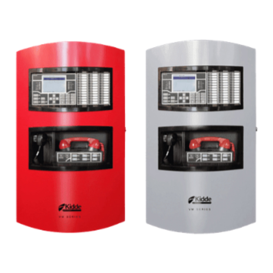
Chapter 1: Introduction System overview The VM-1 control panel can operate as a stand-alone panel or as part of a 24-node VM-1 life safety network. The VM-1 user interface contains operator controls and indicators that make you aware of event activations and provide you with the ability to take action. When... -
Page 13: Overview Of Panel Controls And Indicators
Live voice and prerecorded audio messaging • Two-way firefighter telephone communication • Connection to a VM-1 life safety network using copper, fiber optics, or both (maximum network size may not exceed 24 nodes) Overview of panel controls and indicators Figure 1: VM-LCD User Interface... - Page 14 (8) Monitor queue: Number of active monitor event messages (9) Trouble queue: Number of active trouble event messages (10) Supervisory queue: Number of active supervisory event messages (11) Alarm queue: Number of active alarm event messages (11) (10) VM-1 User Guide...
- Page 15 Serves as a common supervisory event indicator. Trouble Serves as a common trouble event indicator. Disable Indicates when a device, card, group, time control, switch, or LED has been manually disabled. CPU Fail Indicates that the VM-CPU module has detected a processor failure. VM-1 User Guide...
- Page 16 Pressing the button activates the drill command function. The LED turns on while the drill is active. Pressing the button a second time stops the drill. Details button Pressing the button displays additional information about the event highlighted on the LCD screen. VM-1 User Guide...
- Page 17 Figure 6: Cursor keypad details (1) Up button (2) Enter button (3) Left button (4) Down button (5) Right button Figure 7: Alphanumeric keypad details (1) Number buttons (2) Backspace button (3) Space button (4) Menus button VM-1 User Guide...
- Page 18 Pressing the button a second time exits the All Call Minus mode. The LED turns on when the system is in All Call Minus mode. VM-1 User Guide...
- Page 19 Pressing the Page To Alert button broadcasts a live voice message to areas configured to receive alert signals. Pressing the button a second time exits the Page To Alert mode. The LED turns on when the system is in Page To Alert mode. VM-1 User Guide...
-
Page 20: System Operation
System operation The basic function of the VM-1 control panel is to monitor status changes in the life safety system and to activate outputs according to the site-specific software. Status change signals, also called events, are classified as follows: •... -
Page 21: Event Messages
Chapter 1: Introduction Event messages The VM-1 control panel uses event messages to identify points that signal a status change. The first line of the event message displays the event number and the event name. The second line displays the message text. The message text is either the address of the point that activated the event or, if programmed, a location description. -
Page 22: User Access Levels
Chapter 1: Introduction User access levels The VM-1 control panel uses access levels to prevent unauthorized users from operating certain controls and menu commands. Access level 1 does not require a password, access levels 2 to 5 do. Operators are restricted to levels 1 and 2. -
Page 23: Using The Paging Microphone
Note: The system automatically cancels the page and returns to its previous condition after a short delay if you do not cancel the page manually. VM-1 User Guide... -
Page 24: Using The Firefighters Telephone
R-Series and K-R-Series remote annunciators that are compatible with the VM-1 life safety system are shown in Figure 10 on page 15 and Figure 11 on page 17. See the R-Series Remote Annunciators and... - Page 25 Control/Indicator Description LCD screen Displays system status, event messages, and event message details. Up button Pressing the Up button scrolls up through the messages in the event message queue and scrolls up through characters for password entry. VM-1 User Guide...
- Page 26 Yellow LED indicates an active supervisory state. Fire Alarm LED Red LED indicates an active fire alarm state. Power LED Green LED indicates the annunciator is energized. [1] Control and indicator is not on the RLCD or K-RLCD remote annunciator. VM-1 User Guide...
- Page 27 Yellow LED indicates an active zone or device trouble state Controls and indicators [1] See items 5 through 15 in Table 6 on page 15 [1] Controls and indicators are not on the RLED24 or K-RLED24 remote expander. VM-1 User Guide...
-
Page 28: Email And Text Communication
Chapter 1: Introduction Email and text communication For VM-1 systems using VM-CU version 1.30 or later, events can be transmitted through any VM-1 control panel with an installed Ethernet card to external devices such as computers and smartphones. Communication occurs over Ethernet using IP services such as email and text messaging through email. - Page 29 Chapter 1: Introduction Figure 13: Text message example VM-1 User Guide...
- Page 30 Chapter 1: Introduction VM-1 User Guide...
-
Page 31: Basic Operating Instructions
Chapter 2 Basic operating instructions Summary This chapter provides instructions for operating the basic features of your VM-1 life safety system. Basic features are those that anyone can operate. Typically, basic features do not require passwords. Content Checking for active points 22... -
Page 32: Checking For Active Points
Chapter 2: Basic operating instructions Checking for active points The VM-1 control panel provides the following status reports to help you find out if any points in the system are in an active or other off-normal state: • All Active Points: Lists all points that are in an active or other off-normal state (trouble, disable, etc.) -
Page 33: Finding Detectors That May Need Servicing
Chapter 2: Basic operating instructions Finding detectors that may need servicing The VM-1 control panel provides the following maintenance reports to help you find out if any addressable smoke detectors need servicing. Any of the reports can be displayed on the LCD screen or printed on a local printer. -
Page 34: Viewing History Reports
3. Enter the panel address (PP). 4. Choose Display and scroll through the report. — or — Choose Print Locally. 5. When finished, press the Backspace button to return to the Reports Menu or press the Menus button to exit. VM-1 User Guide... -
Page 35: Finding Firmware And Database Version Numbers
Menus button to exit. Viewing the alarm count The VM-1 control panel records how many times it went into the alarm condition. During normal operation, the alarm count is displayed on the LCD. When the VM-1 user interface displays the off-normal screen, you must run a Revisions report to see the alarm count. -
Page 36: Determining Panel Tcp/Ip Settings
NFPA 72 configuration requirements. The report does not indicate why the VM-DACT may be noncompliant. To view the DACT Compliance report: 1. From the Main Menu, choose Reports, and then choose DACT Compliance. 2. Enter the panel address (PP). VM-1 User Guide... -
Page 37: Silencing The Panel Buzzer
Menus button to exit. Silencing the panel buzzer The VM-1 control panel sounds the panel buzzer when an event message is posted into one of the event message queues. Pressing the Ack/Panel Silence button or acknowledging the event message silences the buzzer. The panel buzzer automatically re-sounds when a new event message is posted or when the panel trouble re-sound timer expires (typically after 24 hours). -
Page 38: Acknowledging Events
Acknowledging events Acknowledging an event confirms that you have seen the event message. When you acknowledge an event, the VM-1 control panel places a check mark and the word “Acknowledged” next to the event. On proprietary systems, you cannot silence the panel until all events have been acknowledged. -
Page 39: Performing A Lamp Test
1. From the Main Menu, choose Test, and then choose Lamp Test. Activating alarm signals manually The VM-1 drill feature lets you activate alarm signals manually without putting the panel into alarm. When you activate a drill, all audible alarm signals turn on and, if configured, all visible alarm signals turn on, but other automatic fire alarm responses are not activated. -
Page 40: Changing The Lcd Screen Language
Use the Toggle Language command on the Program Menu to toggle the LCD screen text to a secondary language. Note: The panel must be configured for a secondary language. To change the LCD screen language: 1. From the Main Menu, choose Program. 2. Choose Toggle Language. VM-1 User Guide... -
Page 41: Advanced Operating Instructions
Advanced operating instructions Summary This chapter provides instructions for operating the advanced features of your VM-1 life safety system. Advanced features alter system operation and require the access level 2 password or greater. Content Changing detector alarm sensitivity 32 Changing event message routes 32... -
Page 42: Changing Detector Alarm Sensitivity
When the time control is restored, event messages are automatically switched back to their primary route settings. To activate alternate message routing: 1. From the Main Menu, choose Activate. 2. Choose Alt Message Route. 3. Enter the access level password. VM-1 User Guide... -
Page 43: Disabling And Enabling Devices
The VM-1 control panel keeps track of how many times you disable and enable a device. You must enable a device the same number of times you disable it in order to return the device to its initial condition. -
Page 44: Disabling And Enabling Zone Groups
The VM-1 control panel keeps track of how many times you disable and enable a zone group. You must enable a zone group the same number of times you disable it in order to return the zone group to its initial condition. -
Page 45: Setting The System Time And Date
Chapter 3: Advanced operating instructions Setting the system time and date The VM-1 control panel incorporates a system clock to time stamp events and to activate time controls. The time is presented in 24-hour format. The date is presented in month-day-year format. -
Page 46: Using A Tcp/Ip Connection To Read From The Panel
Using a TCP/IP connection to read from the panel If your VM-1 control panel is equipped with an Ethernet card, your service provider can use the TCP/IP connection to read status and diagnostic information from the panel instead of using an RS-232 connection. By default, this feature is “unlocked.”... -
Page 47: Testing A Carbon Monoxide (Co) Detector
CO in the bloodstream. • If you do not restore the response mode, CO detection returns to its normal response time after 4 hours. To change the CO rate of detection: 1. From the Main Menu, choose Activate. VM-1 User Guide... - Page 48 3. Enter the access level password. To restore the CO rate of detection: 1. From the Main Menu, choose Restore. 2. Choose Gas Accel Response, and then enter the device address (PPCCDDDD). 3. Enter the access level password. VM-1 User Guide...
-
Page 49: Chapter 4 Preventive Maintenance And Testing
Chapter 4 Preventive maintenance and testing Summary This chapter provides instructions for maintaining and testing your VM-1 life safety system. Content Introduction 40 Service provider information 40 Visual inspection schedule 41 Routine maintenance schedule 42 Troubleshooting 43 VM-1 User Guide... -
Page 50: Introduction
Introduction Periodic visual inspections and maintenance testing must be performed on your VM-1 life safety system to ensure that it is operating correctly and as required by the local authority having jurisdiction (AHJ). Maintenance testing is performed by your service provider or a qualified technician with a complete understanding of the system hardware and functions. -
Page 51: Visual Inspection Schedule
Inspect the equipment for any visible signs of damage or other changes that may adversely affect performance. Heat detectors Semiannually Inspect the equipment for any visible signs of damage or other changes that may adversely affect performance. Clean if necessary. VM-1 User Guide... - Page 52 Routine maintenance schedule Routine maintenance and testing should be scheduled for your VM-1 life safety system in accordance with Table 9 below or more often if required by the local AHJ.
-
Page 53: Troubleshooting
[2] Replace batteries every five years, or sooner if conditions warrant. Troubleshooting Problems with your VM-1 life safety system can generally be classified in two categories: application programming problems and hardware (including firmware) problems. Many times hardware problems are identified by the system itself. - Page 54 Chapter 4: Preventive maintenance and testing VM-1 User Guide...
-
Page 55: Appendix A System Addressing
System addressing Summary This appendix provides an easy way to look up card and device addresses. Content Address formats 46 Card address 46 Hardware layer device addresses 48 Operator layer device address 49 Remote annunciator device addresses 50 VM-1 User Guide... -
Page 56: Address Formats
Appendix A: System addressing Address formats VM-1 addresses are in PPCCDDDD format, where: • PP is the cabinet number. Possible values are: 01 (single panel systems) or 01 to 08 (networked systems). • CC is the card’s logical address. Possible values are listed in Table 10. - Page 57 Appendix A: System addressing Figure 14: Logical addresses for a VM-1 with a VM-PMI and a VM-MFK PP02 PP03 PP05 LINE 1 LINE 2 PP35 PP04 PP06 PP07 PP08 PP09 PP10 AUDIO AUX OUT AUX IN AUDIO TELEPHONE RISER DATA...
-
Page 58: Hardware Layer Device Addresses
Appendix A: System addressing Hardware layer device addresses Table 11 below lists the device addresses for points on the VM-1 hardware layer. Table 11: VM-1 hardware layer device addresses Card Device or circuit Address PS10-4B NAC/AUX 1 PP020001 NAC/AUX 2... -
Page 59: Operator Layer Device Address
Appendix A: System addressing Operator layer device address Figure 15 identifies the LEDs and switches on a D12LS-VM card. Table 12 lists the device addresses for the points on the VM-1 operator layer. Figure 15: D12LS-VM LED and switch numbering LED01... -
Page 60: Remote Annunciator Device Addresses
Figure 16: RLED-C / K-RLED-C and RLED24 / K-RLED24 LED numbering LED01 LED17 LED16 LED32 Power Fire Alarm Supervisory Ground Fault Trouble Controls Enabled Ack/Silence RLED-C / K-RLED-C Reset Signal Silence Drill Lamp Test LED01 LED17 LED33 LED16 LED32 LED48 RLED24 / K-RLED24 VM-1 User Guide... - Page 61 Appendix A: System addressing Figure 17: GCI and GCI-NB cards LED and switch numbering VM-1 User Guide...
- Page 62 GCIX LED25 SW24 LED26 SW23 LED27 SW22 LED28 SW21 LED29 SW20 LED30 SW19 LED31 SW18 LED32 SW17 LED33 SW16 LED34 SW15 LED35 SW14 LED36 SW13 LED37 LED48 LED38 LED47 LED39 LED46 LED40 LED45 LED44 LED43 LED42 LED41 VM-1 User Guide...
- Page 63 PP041701 to PP041732 or GCI(-NB) SW01 to SW16 PP021749 to PP041764 Expander 1 LED01 to LED48 PP041801 to PP041848 SW01 to SW24 PP041849 to PP041872 Expander 2 LED01 to LED48 PP041901 to PP041948 SW01 to SW24 PP041949 to PP041972 VM-1 User Guide...
- Page 64 PP043501 to PP043532 or GCI(-NB) SW01 to SW16 PP043549 to PP043564 Expander 1 LED01 to LED48 PP043601 to PP043648 SW01 to SW24 PP043649 to PP043672 Expander 2 LED01 to LED48 PP043701 to PP043748 SW01 to SW24 PP043749 to PP043772 VM-1 User Guide...
- Page 65 PP045301 to PP045332 or GCI(-NB) SW01 to SW16 PP045349 to PP045364 Expander 1 LED01 to LED48 PP045401 to PP045448 SW01 to SW24 PP045449 to PP045472 Expander 2 LED01 to LED48 PP045501 to PP045548 SW01 to SW24 PP045549 to PP045572 VM-1 User Guide...
- Page 66 PP047101 to PP047132 or GCI(-NB) SW01 to SW16 PP047149 to PP047164 Expander 1 LED01 to LED48 PP047201 to PP047248 SW01 to SW24 PP047249 to PP047272 Expander 2 LED01 to LED48 PP047301 to PP047348 SW01 to SW24 PP047349 to PP047372 VM-1 User Guide...
- Page 67 PP048901 to PP048932 or GCI(-NB) SW01 to SW16 PP048949 to PP048964 Expander 1 LED01 to LED48 PP049001 to PP049048 SW01 to SW24 PP049049 to PP049072 Expander 2 LED01 to LED48 PP049101 to PP049148 SW01 to SW24 PP049149 to PP049172 VM-1 User Guide...
- Page 68 Appendix A: System addressing VM-1 User Guide...
-
Page 69: Glossary
The LCD screen shows event messages and system LEDs indicate off-normal statuses. output A signal generated by the system, based upon responses defined in the system database, and sent to external field devices. Outputs are LEDs, and modules. VM-1 User Guide... - Page 70 A serial communications format normally used for serial peripheral devices (i.e., printers) from a computer. SMTP Simple Mail Transfer Protocol. The Internet standard for email transmission. VM-CU Configuration Utility. A Windows-based program used to enter and modify information contained in the system. VM-1 User Guide...
-
Page 71: Index
32 Drill button, 6 CO detection, 37 change rate, 37 restore rate, 38 common controls, 6 email messages, 18 controls and indicators enabling K-RLCD, 15 devices, 34 K-RLCD-C, 15 zone groups, 34 K-RLED, 17 event messages, 11 VM-1 User Guide... - Page 72 41 messaging schedule email, 18 routine maintenance, 42 text through email, 18 visual inspection, 41 microphone, 8, 9 screen language, 30 local, 13 selecting Monitor LED, 5 alternate alarm sensitivity, 32 monitor report, 22 VM-1 User Guide...
- Page 73 36 settings, 26 telephone, 9 test lamp test, 29 preventive maintenance, 40 report, 22 Test LED, 5 text messages through email, 18 time, 35 Trouble LED, 5 trouble report, 22 troubleshooting, 43 user access levels, 12 VM-1 User Guide...
- Page 74 Index VM-1 User Guide...
Need help?
Do you have a question about the VM-1 and is the answer not in the manual?
Questions and answers
I have no manual for the VM-1 and I **** the only custodian at my facility so I have to wing this. How do I check/reset a beeping system that reads “Trouble 0098” photo attached.